Lexus RX (RX 350L, RX450h) 2016-2026 Repair Manual: NTSC Disconnected (from Park Assist/Monitoring ECU) (B1535,C1622)
DESCRIPTION
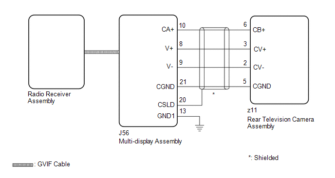
These DTCs are stored if the radio receiver assembly judges that the signals or signal lines between the rear television camera assembly and the multi-display assembly are not normal as a result of its self check.
| DTC No. | Detection Item | DTC Detection Condition | Trouble Area |
|---|---|---|---|
| B1535 | NTSC Disconnected (from Park Assist/Monitoring ECU) | Open or short in the rear television camera assembly signal circuit |
|
| C1622 | Back Camera Disconnected | Open or short in the rear television camera assembly signal circuit |
|
WIRING DIAGRAM
CAUTION / NOTICE / HINT
NOTICE:
-
If the cable was disconnected from and reconnected to the negative (-) battery terminal, the estimated course lines may not be displayed on the image of the area behind the vehicle. In this case, perform "Correct the Steering Angle Neutral Point".
Click here
.gif)
-
Depending on the parts that are replaced or operations that are performed during vehicle inspection or maintenance, calibration of other systems as well as the parking assist monitor system may be needed.
Click here
-
Depending on the parts that are replaced during vehicle inspection or maintenance, performing initialization, registration or calibration may be needed. Refer to Precaution for Navigation System.
Click here
PROCEDURE
| 1. | CHECK DTC |
(a) Clear the DTCs.
Body Electrical > Navigation System > Clear DTCs(b) Turn the engine switch off.
(c) Turn the engine switch on (IG).
(d) Change the shift position to R and check for DTCs.
Body Electrical > Navigation System > Trouble CodesOK:
No DTCs are output.
| OK |  | USE SIMULATION METHOD TO CHECK |
|

| 2. | CHECK HARNESS AND CONNECTOR (REAR TELEVISION CAMERA ASSEMBLY - MULTI-DISPLAY ASSEMBLY) |
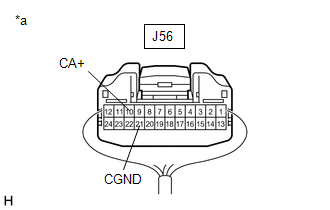
(a) Disconnect the J56 multi-display assembly connector.
(b) Disconnect the z11 rear television camera assembly connector.
(c) Measure the resistance according to the value(s) in the table below.
Standard Resistance:
| Tester Connection | Condition | Specified Condition |
|---|---|---|
| J56-10 (CA+) - z11-6 (CB+) | Always | Below 1 Ω |
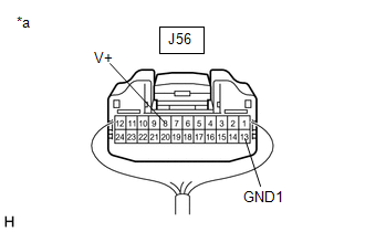
| J56-8 (V+) - z11-3 (CV+) | Always | Below 1 Ω |
| J56-9 (V-) - z11-2 (CV-) | Always | Below 1 Ω |
| J56-21 (CGND) - z11-5 (CGND) | Always | Below 1 Ω |
| J56-10 (CA+) or z11-6 (CB+) - Body ground | Always | 10 kΩ or higher |
| J56-8 (V+) or z11-3 (CV+) - Body ground | Always | 10 kΩ or higher |
| J56-9 (V-) or z11-2 (CV-) - Body ground | Always | 10 kΩ or higher |
| J56-21 (CGND) or z11-5 (CGND) - Body ground | Always | 10 kΩ or higher |
| J56-20 (CSLD) - Body ground | Always | 10 kΩ or higher |
| NG | | REPAIR OR REPLACE HARNESS OR CONNECTOR |
|
| 3. | INSPECT MULTI-DISPLAY ASSEMBLY |
(a) Reconnect the J56 multi-display assembly connector.
| (b) Measure the resistance according to the value(s) in the table below. Standard Resistance:
|
|
(c) Measure the voltage according to the value(s) in the table below.
Standard Voltage:
| Tester Connection | Condition | Specified Condition |
|---|---|---|
| J56-10 (CA+) - J56-21 (CGND) | Engine switch on (ACC) | 5.5 to 7.05 V |
| NG | | REPLACE MULTI-DISPLAY ASSEMBLY |
|
| 4. | INSPECT MULTI-DISPLAY ASSEMBLY |
(a) Reconnect the z11 rear television camera assembly connector.
(b) Using an oscilloscope, check the waveform of the rear television camera assembly.
| *a | Component with harness connected (Multi-display Assembly) |
HINT:
A waterproof connector is used for the rear television camera assembly. Therefore, inspect the waveform at the multi-display assembly with the connector connected.
OK:
Waveform is similar to that shown in the illustration.
| Item | Content |
| Measurement terminal | J56-8 (V+) - J56-13 (GND1) |
| Measurement setting | 200 mV/DIV., 50 μs./DIV. |
| Condition | Engine switch on (IG), shift lever in R |
HINT:
- The video waveform changes according to the image sent by the rear television camera assembly.
- The video waveform is constantly output when the engine switch is on (ACC).
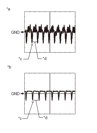
| *a | Waveform 1 (camera lens is not covered, displaying an image) |
| *b | Waveform 2 (camera lens is covered, blacking out the screen) |
| *c | Synchronization Signal |
| *d | Video Waveform |
| NG | | REPLACE REAR TELEVISION CAMERA ASSEMBLY |
|
| 5. | REPLACE MULTI-DISPLAY ASSEMBLY |
(a) Replace the multi-display assembly with a new or known good one.
Click here
|
| 6. | CHECK DTC OUTPUT |
(a) Clear the DTCs.
Body Electrical > Navigation System > Clear DTCs(b) Turn the engine switch off.
(c) Turn the engine switch on (IG).
(d) Change the shift position to R and check for DTCs.
Body Electrical > Navigation System > Trouble CodesOK:
No DTCs are output.
| OK | | END |
| NG | | REPLACE RADIO RECEIVER ASSEMBLY |
 Lost Communication with Haptic Device (B1323-B1326)
DESCRIPTION These DTCs are stored when communication between the radio receiver assembly and remote touch (remote operation controller assembly), combination meter assembly, headup display (meter mirr ...
 GVIF Disconnected (from Extension Module to H/U) (B153A)
DESCRIPTION The radio receiver assembly and navigation ECU are connected via video signal (digital) lines. This DTC is stored when a video signal (digital) line is disconnected. DTC No. Detection ...
Other materials:
Lexus RX (RX 350L, RX450h) 2016-2026 Repair Manual > Power Steering System: Vehicle Speed Signal (C1541)
DESCRIPTION The power steering ECU assembly receives vehicle speed signals from the skid control ECU (brake actuator assembly) via CAN communication. The ECU provides appropriate assist force in accordance with the vehicle speed based on the signals. DTC No. Detection Item DTC Detection Condi ...
Lexus RX (RX 350L, RX450h) 2016-2026 Repair Manual > Intelligent Clearance Sonar System: Communication Error From Clearance Sonar ECU to VSC (C164B)
DESCRIPTION The vehicle stability control system receives intelligent clearance sonar system information from the clearance warning ECU assembly via CAN communication. When it is determined that there is a communication error between the skid control ECU and clearance warning ECU assembly, DTC C164B ...
Lexus RX (RX 350L, RX450h) 2016-{YEAR} Owners Manual
- For your information
- Pictorial index
- For safety and security
- Instrument cluster
- Operation of each component
- Driving
- Lexus Display Audio system
- Interior features
- Maintenance and care
- When trouble arises
- Vehicle specifications
- For owners
Lexus RX (RX 350L, RX450h) 2016-{YEAR} Repair Manual

0.0125