Lexus RX (RX 350L, RX450h) 2016-2026 Repair Manual: Terminals Of Ecu
TERMINALS OF ECU
CHECK MULTIPLEX NETWORK MASTER SWITCH ASSEMBLY

(a) Disconnect the N7 multiplex network master switch assembly connector.
(b) Measure the voltage and resistance according to the value(s) in the table below.
HINT:
Measure the values on the wire harness side with the connector disconnected.
| Terminal No. (Symbol) | Wiring Color | Terminal Description | Condition | Specified Condition |
|---|---|---|---|---|
| N7-11 (B) - N7-12 (GND) | B - W-B | Power supply | Always | 11 to 14 V |
| N7-12 (GND) - Body ground | W-B - Body ground | Ground | Always | Below 1 Ω |
(c) Reconnect the N7 multiplex network master switch assembly connector.
(d) Measure the voltage according to the value(s) in the table below.
| Terminal No. (Symbol) | Wiring Color | Terminal Description | Condition | Specified Condition |
|---|---|---|---|---|
| N7-15 (DOWN) - N7-12 (GND) | B - W-B | Power window motor DOWN output | Engine switch on (IG), driver door power window regulator switch not pushed or pulled | 11 to 14 V |
| N7-15 (DOWN) - N7-12 (GND) | B - W-B | Power window motor DOWN output | Engine switch on (IG), driver door power window moving, driver door power window regulator switch pushed halfway down (Manual operation) | Below 1 V |
| N7-20 (UP) - N7-12 (GND) | G - W-B | Power window motor UP output | Engine switch on (IG), driver door power window regulator switch not pushed or pulled | 11 to 14 V |
| N7-20 (UP) - N7-12 (GND) | G - W-B | Power window motor UP output | Engine switch on (IG), driver door power window moving, driver door power window regulator switch pulled halfway up (Manual operation) | Below 1 V |
CHECK POWER WINDOW REGULATOR SWITCH ASSEMBLY

(a) Disconnect the M6 power window regulator switch assembly connector.
(b) Measure the resistance according to the value(s) in the table below.
HINT:
Measure the values on the wire harness side with the connector disconnected.
| Terminal No. (Symbol) | Wiring Color | Terminal Description | Condition | Specified Condition |
|---|---|---|---|---|
| M6-5 (GND) - Body ground | W-B - Body ground | Ground | Always | Below 1 Ω |
(c) Reconnect the M6 power window regulator switch assembly connector.
(d) Measure the voltage according to the value(s) in the table below.
| Terminal No. (Symbol) | Wiring Color | Terminal Description | Condition | Specified Condition |
|---|---|---|---|---|
| M6-8 (LED) - M6-5 (GND) | L - W-B | LED illumination signal | Engine switch on (IG) | 11 to 14 V |
| M6-8 (LED) - M6-5 (GND) | L - W-B | LED illumination signal | Engine switch off | Below 1 V |
| M6-2 (UP) - M6-5 (GND) | R - W-B | Power window motor UP output | Engine switch on (IG), power window regulator switch assembly not pushed or pulled | 11 to 14 V |
| M6-2 (UP) - M6-5 (GND) | R - W-B | Power window motor UP output | Engine switch on (IG), front passenger door power window moving, power window regulator switch assembly pulled halfway up (Manual operation) | Below 1 V |
| M6-2 (UP) - M6-5 (GND) | R - W-B | Power window motor UP output | Engine switch on (IG), front passenger door power window fully open | 11 to 14 V |
| M6-2 (UP) - M6-5 (GND) | R - W-B | Power window motor UP output | Engine switch on (IG), front passenger door power window moving, power window regulator switch assembly fully pulled up (Auto operation) | Below 1 V |
| M6-2 (UP) - M6-5 (GND) | R - W-B | Power window motor UP output | Engine switch on (IG), front passenger door power window fully closed | 11 to 14 V |
| M6-10 (DOWN) - M6-5 (GND) | B - W-B | Power window motor DOWN output | Engine switch on (IG), power window regulator switch assembly not pushed or pulled | 11 to 14 V |
| M6-10 (DOWN) - M6-5 (GND) | B - W-B | Power window motor DOWN output | Engine switch on (IG), front passenger door power window moving, power window regulator switch assembly pushed halfway down (Manual operation) | Below 1 V |
| M6-10 (DOWN) - M6-5 (GND) | B - W-B | Power window motor DOWN output | Engine switch on (IG), front passenger door power window fully closed | 11 to 14 V |
| M6-10 (DOWN) - M6-5 (GND) | B - W-B | Power window motor DOWN output | Engine switch on (IG), front passenger door power window moving, power window regulator switch assembly fully pushed down (Auto operation) | Below 1 V |
| M6-10 (DOWN) - M6-5 (GND) | B - W-B | Power window motor DOWN output | Engine switch on (IG), front passenger door power window fully open | 11 to 14 V |
| M6-4 (AUTO) - M6-5 (GND) | Y - W-B | Power window motor AUTO UP output | Engine switch on (IG), front passenger door power window fully open | 11 to 14 V |
| M6-4 (AUTO) - M6-5 (GND) | Y - W-B | Power window motor AUTO UP output | Engine switch on (IG), front passenger door power window moving, power window regulator switch assembly fully pulled up (Auto operation) | Below 1 V |
| M6-4 (AUTO) - M6-5 (GND) | Y - W-B | Power window motor AUTO UP output | Engine switch on (IG), front passenger door power window fully closed | 11 to 14 V |
| M6-4 (AUTO) - M6-5 (GND) | Y - W-B | Power window motor AUTO DOWN output | Engine switch on (IG), front passenger door power window fully closed | 11 to 14 V |
| M6-4 (AUTO) - M6-5 (GND) | Y - W-B | Power window motor AUTO DOWN output | Engine switch on (IG), front passenger door power window moving, power window regulator switch assembly fully pushed down (Auto operation) | Below 1 V |
| M6-4 (AUTO) - M6-5 (GND) | Y - W-B | Power window motor AUTO DOWN output | Engine switch on (IG), front passenger door power window fully open | 11 to 14 V |
CHECK REAR POWER WINDOW REGULATOR SWITCH ASSEMBLY (FOR LH DOOR)

(a) Disconnect the Q2 rear power window regulator switch assembly (for LH door) connector.
(b) Measure the resistance according to the value(s) in the table below.
HINT:
Measure the values on the wire harness side with the connector disconnected.
| Terminal No. (Symbol) | Wiring Color | Terminal Description | Condition | Specified Condition |
|---|---|---|---|---|
| Q2-5 (GND) - Body ground | W-B - Body ground | Ground | Always | Below 1 Ω |
(c) Reconnect the Q2 rear power window regulator switch assembly (for LH door) connector.
(d) Measure the voltage according to the value(s) in the table below.
| Terminal No. (Symbol) | Wiring Color | Terminal Description | Condition | Specified Condition |
|---|---|---|---|---|
| Q2-8 (LED) - Q2-5 (GND) | G - W-B | LED illumination signal | Engine switch on (IG) | 11 to 14 V |
| Q2-8 (LED) - Q2-5 (GND) | G - W-B | LED illumination signal | Engine switch off | Below 1 V |
| Q2-2 (UP) - Q2-5 (GND) | V - W-B | Power window motor UP output | Engine switch on (IG), rear power window regulator switch assembly (for LH door) not pushed or pulled | 11 to 14 V |
| Q2-2 (UP) - Q2-5 (GND) | V - W-B | Power window motor UP output | Engine switch on (IG), rear LH door power window moving, rear power window regulator switch assembly (for LH door) pulled halfway up (Manual operation) | Below 1 V |
| Q2-2 (UP) - Q2-5 (GND) | V - W-B | Power window motor UP output | Engine switch on (IG), rear LH door power window fully open | 11 to 14 V |
| Q2-2 (UP) - Q2-5 (GND) | V - W-B | Power window motor UP output | Engine switch on (IG), rear LH door power window moving, rear power window regulator switch assembly (for LH door) fully pulled up (Auto operation) | Below 1 V |
| Q2-2 (UP) - Q2-5 (GND) | V - W-B | Power window motor UP output | Engine switch on (IG), rear LH door power window fully closed | 11 to 14 V |
| Q2-10 (DOWN) - Q2-5 (GND) | W - W-B | Power window motor DOWN output | Engine switch on (IG), rear power window regulator switch assembly (for LH door) not pushed or pulled | 11 to 14 V |
| Q2-10 (DOWN) - Q2-5 (GND) | W - W-B | Power window motor DOWN output | Engine switch on (IG), rear LH door power window moving, rear power window regulator switch assembly (for LH door) pushed halfway down (Manual operation) | Below 1 V |
| Q2-10 (DOWN) - Q2-5 (GND) | W - W-B | Power window motor DOWN output | Engine switch on (IG), rear LH door power window fully closed | 11 to 14 V |
| Q2-10 (DOWN) - Q2-5 (GND) | W - W-B | Power window motor DOWN output | Engine switch on (IG), rear LH door power window moving, rear power window regulator switch assembly (for LH door) fully pushed down (Auto operation) | Below 1 V |
| Q2-10 (DOWN) - Q2-5 (GND) | W - W-B | Power window motor DOWN output | Engine switch on (IG), rear LH door power window fully open | 11 to 14 V |
| Q2-4 (AUTO) - Q2-5 (GND) | B - W-B | Power window motor AUTO UP output | Engine switch on (IG), rear LH door power window fully open | 11 to 14 V |
| Q2-4 (AUTO) - Q2-5 (GND) | B - W-B | Power window motor AUTO UP output | Engine switch on (IG), rear LH door power window moving, rear power window regulator switch assembly (for LH door) fully pulled up (Auto operation) | Below 1 V |
| Q2-4 (AUTO) - Q2-5 (GND) | B - W-B | Power window motor AUTO UP output | Engine switch on (IG), rear LH door power window fully closed | 11 to 14 V |
| Q2-4 (AUTO) - Q2-5 (GND) | B - W-B | Power window motor AUTO DOWN output | Engine switch on (IG), rear LH door power window fully closed | 11 to 14 V |
| Q2-4 (AUTO) - Q2-5 (GND) | B - W-B | Power window motor AUTO DOWN output | Engine switch on (IG), rear LH door power window moving, rear power window regulator switch assembly (for LH door) fully pushed down (Auto operation) | Below 1 V |
| Q2-4 (AUTO) - Q2-5 (GND) | B - W-B | Power window motor AUTO DOWN output | Engine switch on (IG), rear LH door power window fully open | 11 to 14 V |
CHECK REAR POWER WINDOW REGULATOR SWITCH ASSEMBLY (FOR RH DOOR)

(a) Disconnect the Q1 rear power window regulator switch assembly (for RH door) connector.
(b) Measure the resistance according to the value(s) in the table below.
HINT:
Measure the values on the wire harness side with the connector disconnected.
| Terminal No. (Symbol) | Wiring Color | Terminal Description | Condition | Specified Condition |
|---|---|---|---|---|
| Q1-5 (GND) - Body ground | W-B - Body ground | Ground | Always | Below 1 Ω |
(c) Reconnect the Q1 rear power window regulator switch assembly (for RH door) connector.
(d) Measure the voltage according to the value(s) in the table below.
| Terminal No. (Symbol) | Wiring Color | Terminal Description | Condition | Specified Condition |
|---|---|---|---|---|
| Q1-8 (LED) - Q1-5 (GND) | G - W-B | LED illumination signal | Engine switch on (IG) | 11 to 14 V |
| Q1-8 (LED) - Q1-5 (GND) | G - W-B | LED illumination signal | Engine switch off | Below 1 V |
| Q1-2 (UP) - Q1-5 (GND) | V - W-B | Power window motor UP output | Engine switch on (IG), rear power window regulator switch assembly (for RH door) not pushed or pulled | 11 to 14 V |
| Q1-2 (UP) - Q1-5 (GND) | V - W-B | Power window motor UP output | Engine switch on (IG), rear RH door power window moving, rear power window regulator switch assembly (for RH door) pulled halfway up (Manual operation) | Below 1 V |
| Q1-2 (UP) - Q1-5 (GND) | V - W-B | Power window motor UP output | Engine switch on (IG), rear RH door power window fully open | 11 to 14 V |
| Q1-2 (UP) - Q1-5 (GND) | V - W-B | Power window motor UP output | Engine switch on (IG), rear RH door power window moving, rear power window regulator switch assembly (for RH door) fully pulled up (Auto operation) | Below 1 V |
| Q1-2 (UP) - Q1-5 (GND) | V - W-B | Power window motor UP output | Engine switch on (IG), rear RH door power window fully closed | 11 to 14 V |
| Q1-10 (DOWN) - Q1-5 (GND) | W - W-B | Power window motor DOWN output | Engine switch on (IG), rear power window regulator switch assembly (for RH door) not pushed or pulled | 11 to 14 V |
| Q1-10 (DOWN) - Q1-5 (GND) | W - W-B | Power window motor DOWN output | Engine switch on (IG), rear RH door power window moving, rear power window regulator switch assembly (for RH door) pushed halfway down (Manual operation) | Below 1 V |
| Q1-10 (DOWN) - Q1-5 (GND) | W - W-B | Power window motor DOWN output | Engine switch on (IG), rear RH door power window fully closed | 11 to 14 V |
| Q1-10 (DOWN) - Q1-5 (GND) | W - W-B | Power window motor DOWN output | Engine switch on (IG), rear RH door power window moving, rear power window regulator switch assembly (for RH door) fully pushed down (Auto operation) | Below 1 V |
| Q1-10 (DOWN) - Q1-5 (GND) | W - W-B | Power window motor DOWN output | Engine switch on (IG), rear RH door power window fully open | 11 to 14 V |
| Q1-4 (AUTO) - Q1-5 (GND) | B - W-B | Power window motor AUTO UP output | Engine switch on (IG), rear RH door power window fully open | 11 to 14 V |
| Q1-4 (AUTO) - Q1-5 (GND) | B - W-B | Power window motor AUTO UP output | Engine switch on (IG), rear RH door power window moving, rear power window regulator switch assembly (for RH door) fully pulled up (Auto operation) | Below 1 V |
| Q1-4 (AUTO) - Q1-5 (GND) | B - W-B | Power window motor AUTO UP output | Engine switch on (IG), rear RH door power window fully closed | 11 to 14 V |
| Q1-4 (AUTO) - Q1-5 (GND) | B - W-B | Power window motor AUTO DOWN output | Engine switch on (IG), rear RH door power window fully closed | 11 to 14 V |
| Q1-4 (AUTO) - Q1-5 (GND) | B - W-B | Power window motor AUTO DOWN output | Engine switch on (IG), rear RH door power window moving, rear power window regulator switch assembly (for RH door) fully pushed down (Auto operation) | Below 1 V |
| Q1-4 (AUTO) - Q1-5 (GND) | B - W-B | Power window motor AUTO DOWN output | Engine switch on (IG), rear RH door power window fully open | 11 to 14 V |
CHECK POWER WINDOW REGULATOR MOTOR ASSEMBLY (FOR DRIVER DOOR)

(a) Disconnect the N13 power window regulator motor assembly (for driver door) connector.
(b) Measure the voltage and resistance according to the value(s) in the table below.
HINT:
Measure the values on the wire harness side with the connector disconnected.
| Terminal No. (Symbol) | Wiring Color | Terminal Description | Condition | Specified Condition |
|---|---|---|---|---|
| N13-1 (E) - Body ground | W-B - Body ground | Ground | Always | Below 1 Ω |
| N13-2 (B) - Body ground | L - Body ground | Power supply | Always | 11 to 14 V |
(c) Reconnect the N13 power window regulator motor assembly (for driver door) connector.
(d) Measure the voltage according to the value(s) in the table below.
| Terminal No. (Symbol) | Wiring Color | Terminal Description | Condition | Specified Condition |
|---|---|---|---|---|
| N13-7 (DWN1) - N13-1 (E) | B - W-B | Power window motor DOWN input | Engine switch on (IG), multiplex network master switch assembly (driver door power window regulator switch) not pushed or pulled | 11 to 14 V |
| N13-7 (DWN1) - N13-1 (E) | B - W-B | Power window motor DOWN input | Engine switch on (IG), driver door power window moving, multiplex network master switch assembly (driver door power window regulator switch) pushed halfway down (Manual operation) | Below 1 V |
| N13-7 (DWN1) - N13-1 (E) | B - W-B | Power window motor DOWN input | Engine switch on (IG), driver door power window fully closed | 11 to 14 V |
| N13-7 (DWN1) - N13-1 (E) | B - W-B | Power window motor DOWN input | Engine switch on (IG), driver door power window moving, multiplex network master switch assembly (driver door power window regulator switch) fully pushed down (Auto operation) | Below 1 V |
| N13-7 (DWN1) - N13-1 (E) | B - W-B | Power window motor DOWN input | Engine switch on (IG), driver door power window fully open | 11 to 14 V |
| N13-10 (UP1) - N13-1 (E) | G - W-B | Power window motor UP input | Engine switch on (IG), multiplex network master switch assembly (driver door power window regulator switch) not pushed or pulled | 11 to 14 V |
| N13-10 (UP1) - N13-1 (E) | G - W-B | Power window motor UP input | Engine switch on (IG), driver door power window moving, multiplex network master switch assembly (driver door power window regulator switch) pulled halfway up (Manual operation) | Below 1 V |
| N13-10 (UP1) - N13-1 (E) | G - W-B | Power window motor UP input | Engine switch on (IG), multiplex network master switch assembly (driver door power window regulator switch) fully open | 11 to 14 V |
| N13-10 (UP1) - N13-1 (E) | G - W-B | Power window motor UP input | Engine switch on (IG), driver door power window moving, multiplex network master switch assembly (driver door power window regulator switch) fully pulled up (Auto operation) | Below 1 V |
| N13-10 (UP1) - N13-1 (E) | G - W-B | Power window motor UP input | Engine switch on (IG), driver door power window fully closed | 11 to 14 V |
CHECK POWER WINDOW REGULATOR MOTOR ASSEMBLY (FOR FRONT PASSENGER DOOR)

(a) Disconnect the M13 power window regulator motor assembly (for front passenger door) connector.
(b) Measure the voltage and resistance according to the value(s) in the table below.
HINT:
Measure the values on the wire harness side with the connector disconnected.
| Terminal No. (Symbol) | Wiring Color | Terminal Description | Condition | Specified Condition |
|---|---|---|---|---|
| M13-1 (E) - Body ground | W-B - Body ground | Ground | Always | Below 1 Ω |
| M13-2 (B) - Body ground | G - Body ground | Power supply | Always | 11 to 14 V |
(c) Reconnect the M13 power window regulator motor assembly (for front passenger door) connector.
(d) Measure the voltage according to the value(s) in the table below.
| Terminal No. (Symbol) | Wiring Color | Terminal Description | Condition | Specified Condition |
|---|---|---|---|---|
| M13-4 (AUTO) - M13-1 (E) | Y - W-B | Power window motor AUTO UP input | Engine switch on (IG), front passenger door power window fully open | 11 to 14 V |
| M13-4 (AUTO) - M13-1 (E) | Y - W-B | Power window motor AUTO UP input | Engine switch on (IG), front passenger door power window moving, power window regulator switch assembly fully pulled up (Auto operation) | Below 1 V |
| M13-4 (AUTO) - M13-1 (E) | Y - W-B | Power window motor AUTO UP input | Engine switch on (IG), front passenger door power window fully closed | 11 to 14 V |
| M13-4 (AUTO) - M13-1 (E) | Y - W-B | Power window motor AUTO DOWN input | Engine switch on (IG), front passenger door power window fully closed | 11 to 14 V |
| M13-4 (AUTO) - M13-1 (E) | Y - W-B | Power window motor AUTO DOWN input | Engine switch on (IG), front passenger door power window moving, power window regulator switch assembly fully pushed down (Auto operation) | Below 1 V |
| M13-4 (AUTO) - M13-1 (E) | Y - W-B | Power window motor AUTO DOWN input | Engine switch on (IG), front passenger door power window fully open | 11 to 14 V |
| M13-5 (LED) - M13-1 (E) | L - W-B | LED illumination signal | Engine switch on (IG) | 11 to 14 V |
| M13-5 (LED) - M13-1 (E) | L - W-B | LED illumination signal | Engine switch off | Below 1 V |
| M13-7 (DWN1) - M13-1 (E) | B - W-B | Power window motor DOWN input | Engine switch on (IG), power window regulator switch assembly not pushed or pulled | 11 to 14 V |
| M13-7 (DWN1) - M13-1 (E) | B - W-B | Power window motor DOWN input | Engine switch on (IG), front passenger door power window moving, power window regulator switch assembly pushed halfway down (Manual operation) | Below 1 V |
| M13-7 (DWN1) - M13-1 (E) | B - W-B | Power window motor DOWN input | Engine switch on (IG), front passenger door power window fully closed | 11 to 14 V |
| M13-7 (DWN1) - M13-1 (E) | B - W-B | Power window motor DOWN input | Engine switch on (IG), front passenger door power window moving, power window regulator switch assembly fully pushed down (Auto operation) | Below 1 V |
| M13-7 (DWN1) - M13-1 (E) | B - W-B | Power window motor DOWN input | Engine switch on (IG), front passenger door power window fully open | 11 to 14 V |
| M13-10 (UP1) - M13-1 (E) | R - W-B | Power window motor UP input | Engine switch on (IG), power window regulator switch assembly not pushed or pulled | 11 to 14 V |
| M13-10 (UP1) - M13-1 (E) | R - W-B | Power window motor UP input | Engine switch on (IG), front passenger door power window moving, power window regulator switch assembly pulled halfway up (Manual operation) | Below 1 V |
| M13-10 (UP1) - M13-1 (E) | R - W-B | Power window motor UP input | Engine switch on (IG), front passenger door power window fully open | 11 to 14 V |
| M13-10 (UP1) - M13-1 (E) | R - W-B | Power window motor UP input | Engine switch on (IG), front passenger door power window moving, power window regulator switch assembly fully pulled up (Auto operation) | Below 1 V |
| M13-10 (UP1) - M13-1 (E) | R - W-B | Power window motor UP input | Engine switch on (IG), front passenger door power window fully closed | 11 to 14 V |
CHECK POWER WINDOW REGULATOR MOTOR ASSEMBLY (FOR REAR LH DOOR)

(a) Disconnect the P1 power window regulator motor assembly (for rear LH door) connector.
(b) Measure the voltage and resistance according to the value(s) in the table below.
HINT:
Measure the values on the wire harness side with the connector disconnected.
| Terminal No. (Symbol) | Wiring Color | Terminal Description | Condition | Specified Condition |
|---|---|---|---|---|
| P1-1 (E) - Body ground | W-B - Body ground | Ground | Always | Below 1 Ω |
| P1-2 (B) - Body ground | L - Body ground | Power supply | Always | 11 to 14 V |
(c) Reconnect the P1 power window regulator motor assembly (for rear LH door) connector.
(d) Measure the voltage according to the value(s) in the table below.
| Terminal No. (Symbol) | Wiring Color | Terminal Description | Condition | Specified Condition |
|---|---|---|---|---|
| P1-4 (AUTO) - P1-1 (E) | B - W-B | Power window motor AUTO UP input | Engine switch on (IG), rear LH door power window fully open | 11 to 14 V |
| P1-4 (AUTO) - P1-1 (E) | B - W-B | Power window motor AUTO UP input | Engine switch on (IG), rear LH door power window moving, rear power window regulator switch assembly (for LH door) fully pulled up (Auto operation) | Below 1 V |
| P1-4 (AUTO) - P1-1 (E) | B - W-B | Power window motor AUTO UP input | Engine switch on (IG), rear LH door power window fully closed | 11 to 14 V |
| P1-4 (AUTO) - P1-1 (E) | B - W-B | Power window motor AUTO DOWN input | Engine switch on (IG), rear LH door power window fully closed | 11 to 14 V |
| P1-4 (AUTO) - P1-1 (E) | B - W-B | Power window motor AUTO DOWN input | Engine switch on (IG), rear LH door power window moving, rear power window regulator switch assembly (for LH door) fully pushed down (Auto operation) | Below 1 V |
| P1-4 (AUTO) - P1-1 (E) | B - W-B | Power window motor AUTO DOWN input | Engine switch on (IG), rear LH door power window fully open | 11 to 14 V |
| P1-5 (LED) - P1-1 (E) | G - W-B | LED illumination signal | Engine switch on (IG) | 11 to 14 V |
| P1-5 (LED) - P1-1 (E) | G - W-B | LED illumination signal | Engine switch off | Below 1 V |
| P1-7 (DWN1) - P1-1 (E) | W - W-B | Power window motor DOWN input | Engine switch on (IG), rear power window regulator switch assembly (for LH door) not pushed or pulled | 11 to 14 V |
| P1-7 (DWN1) - P1-1 (E) | W - W-B | Power window motor DOWN input | Engine switch on (IG), rear LH door power window moving, rear power window regulator switch assembly (for LH door) pushed halfway down (Manual operation) | Below 1 V |
| P1-7 (DWN1) - P1-1 (E) | W - W-B | Power window motor DOWN input | Engine switch on (IG), rear LH door power window fully closed | 11 to 14 V |
| P1-7 (DWN1) - P1-1 (E) | W - W-B | Power window motor DOWN input | Engine switch on (IG), rear LH door power window moving, rear power window regulator switch assembly (for LH door) fully pushed down (Auto operation) | Below 1 V |
| P1-7 (DWN1) - P1-1 (E) | W - W-B | Power window motor DOWN input | Engine switch on (IG), rear LH door power window fully open | 11 to 14 V |
| P1-10 (UP1) - P1-1 (E) | V - W-B | Power window motor UP input | Engine switch on (IG), rear power window regulator switch assembly (for LH door) not pushed or pulled | 11 to 14 V |
| P1-10 (UP1) - P1-1 (E) | V - W-B | Power window motor UP input | Engine switch on (IG), rear LH door power window moving, rear power window regulator switch assembly (for LH door) pulled halfway up (Manual operation) | Below 1 V |
| P1-10 (UP1) - P1-1 (E) | V - W-B | Power window motor UP input | Engine switch on (IG), rear LH door power window fully open | 11 to 14 V |
| P1-10 (UP1) - P1-1 (E) | V - W-B | Power window motor UP input | Engine switch on (IG), rear LH door power window moving, rear power window regulator switch assembly (for LH door) fully pulled up (Auto operation) | Below 1 V |
| P1-10 (UP1) - P1-1 (E) | V - W-B | Power window motor UP input | Engine switch on (IG), rear LH door power window fully closed | 11 to 14 V |
CHECK POWER WINDOW REGULATOR MOTOR ASSEMBLY (FOR REAR RH DOOR)

(a) Disconnect the O1 power window regulator motor assembly (for rear RH door) connector.
(b) Measure the voltage and resistance according to the value(s) in the table below.
HINT:
Measure the values on the wire harness side with the connector disconnected.
| Terminal No. (Symbol) | Wiring Color | Terminal Description | Condition | Specified Condition |
|---|---|---|---|---|
| O1-1 (E) - Body ground | W-B - Body ground | Ground | Always | Below 1 Ω |
| O1-2 (B) - Body ground | P - Body ground | Power supply | Always | 11 to 14 V |
(c) Reconnect the O1 power window regulator motor assembly (for rear RH door) connector.
(d) Measure the voltage according to the value(s) in the table below.
| Terminal No. (Symbol) | Wiring Color | Terminal Description | Condition | Specified Condition |
|---|---|---|---|---|
| O1-4 (AUTO) - O1-1 (E) | B - W-B | Power window motor AUTO UP input | Engine switch on (IG), rear RH door power window fully open | 11 to 14 V |
| O1-4 (AUTO) - O1-1 (E) | B - W-B | Power window motor AUTO UP input | Engine switch on (IG), rear RH door power window moving, rear power window regulator switch assembly (for RH door) fully pulled up (Auto operation) | Below 1 V |
| O1-4 (AUTO) - O1-1 (E) | B - W-B | Power window motor AUTO UP input | Engine switch on (IG), rear RH door power window fully closed | 11 to 14 V |
| O1-4 (AUTO) - O1-1 (E) | B - W-B | Power window motor AUTO DOWN input | Engine switch on (IG), rear RH door power window fully closed | 11 to 14 V |
| O1-4 (AUTO) - O1-1 (E) | B - W-B | Power window motor AUTO DOWN input | Engine switch on (IG), rear RH door power window moving, rear power window regulator switch assembly (for RH door) fully pushed down (Auto operation) | Below 1 V |
| O1-4 (AUTO) - O1-1 (E) | B - W-B | Power window motor AUTO DOWN input | Engine switch on (IG), rear RH door power window fully open | 11 to 14 V |
| O1-5 (LED) - O1-1 (E) | G - W-B | LED illumination signal | Engine switch on (IG) | 11 to 14 V |
| O1-5 (LED) - O1-1 (E) | G - W-B | LED illumination signal | Engine switch off | Below 1 V |
| O1-7 (DWN1) - O1-1 (E) | W - W-B | Power window motor DOWN input | Engine switch on (IG), rear power window regulator switch assembly (for RH door) not pushed or pulled | 11 to 14 V |
| O1-7 (DWN1) - O1-1 (E) | W - W-B | Power window motor DOWN input | Engine switch on (IG), rear RH door power window moving, rear power window regulator switch assembly (for RH door) pushed halfway down (Manual operation) | Below 1 V |
| O1-7 (DWN1) - O1-1 (E) | W - W-B | Power window motor DOWN input | Engine switch on (IG), rear RH door power window fully closed | 11 to 14 V |
| O1-7 (DWN1) - O1-1 (E) | W - W-B | Power window motor DOWN input | Engine switch on (IG), rear RH door power window moving, rear power window regulator switch assembly (for RH door) fully pushed down (Auto operation) | Below 1 V |
| O1-7 (DWN1) - O1-1 (E) | W - W-B | Power window motor DOWN input | Engine switch on (IG), rear RH door power window fully open | 11 to 14 V |
| O1-10 (UP1) - O1-1 (E) | V - W-B | Power window motor UP input | Engine switch on (IG), rear power window regulator switch assembly (for RH door) not pushed or pulled | 11 to 14 V |
| O1-10 (UP1) - O1-1 (E) | V - W-B | Power window motor UP input | Engine switch on (IG), rear RH door power window moving, rear power window regulator switch assembly (for RH door) pulled halfway up (Manual operation) | Below 1 V |
| O1-10 (UP1) - O1-1 (E) | V - W-B | Power window motor UP input | Engine switch on (IG), rear RH door power window fully open | 11 to 14 V |
| O1-10 (UP1) - O1-1 (E) | V - W-B | Power window motor UP input | Engine switch on (IG), rear RH door power window moving, rear power window regulator switch assembly (for RH door) fully pulled up (Auto operation) | Below 1 V |
| O1-10 (UP1) - O1-1 (E) | V - W-B | Power window motor UP input | Engine switch on (IG), rear RH door power window fully closed | 11 to 14 V |
CHECK INSTRUMENT PANEL JUNCTION BLOCK ASSEMBLY AND MAIN BODY ECU (MULTIPLEX NETWORK BODY ECU)
(a) Remove the main body ECU (multiplex network body ECU) from the instrument panel junction block assembly.
(b) Reconnect the instrument panel junction block assembly connectors.
(c) Measure the voltage and resistance according to the value(s) in the table below.
HINT:
Measure the values on the wire harness side with the connectors connected.
| Terminal No. (Symbol) | Wiring Color | Terminal Description | Condition | Specified Condition |
|---|---|---|---|---|
| MB-11 (GND1) - Body ground | - | Ground | Always | Below 1 Ω |
| MB-31 (BECU) - Body ground | - | Battery power supply | Always | 11 to 14 V |
| MB-30 (ACC) - Body ground | - | ACC power supply | Engine switch on (ACC) | 11 to 14 V |
| MB-30 (ACC) - Body ground | - | ACC power supply | Engine switch off | Below 1 V |
| MB-32 (IG) - Body ground | - | IG power supply | Engine switch on (IG) | 11 to 14 V |
| MB-32 (IG) - Body ground | - | IG power supply | Engine switch off | Below 1 V |
(d) Install the main body ECU (multiplex network body ECU) to the instrument panel junction block assembly.
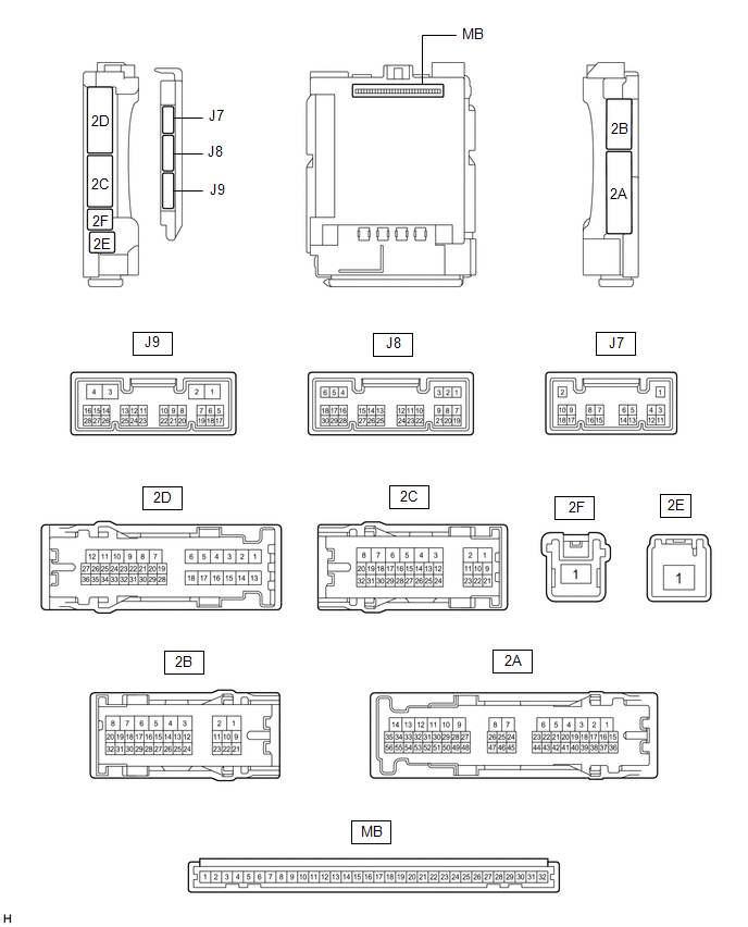
(e) Measure the voltage and check for pulses according to the value(s) in the table below.
| Terminal No. (Symbol) | Wiring Color | Terminal Description | Condition | Specified Condition |
|---|---|---|---|---|
| J8-6 (FLCY) - Body ground | P - Body ground | Front door courtesy light switch assembly (for LH) input | Front door LH open | Below 1 V |
| J8-6 (FLCY) - Body ground | P - Body ground | Front door courtesy light switch assembly (for LH) input | Front door LH closed | 11 to 14 V |
| J8-27 (FRCY) - Body ground | R - Body ground | Front door courtesy light switch assembly (for RH) input | Front door RH open | Below 1 V |
| J8-27 (FRCY) - Body ground | R - Body ground | Front door courtesy light switch assembly (for RH) input | Front door RH closed | 11 to 14 V |
| J8-29 (L2) - Body ground | P - Body ground | Driver door key-linked lock input | Driver door key cylinder turned to lock | Below 1 V |
| J8-29 (L2) - Body ground | P - Body ground | Driver door key-linked lock input | Driver door key cylinder not turned | Pulse generation |
| J8-2 (UL3) - Body ground | V - Body ground | Driver door key-linked unlock input | Driver door key cylinder turned to unlock | Below 1 V |
| J8-2 (UL3) - Body ground | V - Body ground | Driver door key-linked unlock input | Driver door key cylinder not turned | Pulse generation |
 Diagnosis System
DIAGNOSIS SYSTEM DESCRIPTION (a) Power window control system data and Diagnostic Trouble Codes (DTCs) can be read through the vehicle Data Link Connector 3 (DLC3). When the system seems to be malfunct ...
 Data List / Active Test
DATA LIST / ACTIVE TEST DATA LIST HINT: Using the Techstream to read the Data List allows the values or states of switches, sensors, actuators and other items to be read without removing any parts. Th ...
Other materials:
Lexus RX (RX 350L, RX450h) 2016-2026 Repair Manual > Blind Spot Monitor System: How To Proceed With Troubleshooting
CAUTION / NOTICE / HINT HINT:
Use the following procedure to troubleshoot the blind spot monitor system.
*: Use the Techstream.
PROCEDURE 1. VEHICLE BROUGHT TO WORKSHOP
NEXT 2. CUSTOMER PROBLEM ANALYSIS HINT: If there are any scratches or impact marks on th ...
Lexus RX (RX 350L, RX450h) 2016-2026 Repair Manual > Cruise Control Main Switch: Inspection
INSPECTION PROCEDURE 1. INSPECT CRUISE CONTROL MAIN SWITCH (a) Measure the resistance according to the value(s) in the table below. *a Component without harness connected (Cruise Control Switch) - - Standard Resistance: Tester Connection Condition Specified Condition 1 (ECC) ...
Lexus RX (RX 350L, RX450h) 2016-{YEAR} Owners Manual
- For your information
- Pictorial index
- For safety and security
- Instrument cluster
- Operation of each component
- Driving
- Lexus Display Audio system
- Interior features
- Maintenance and care
- When trouble arises
- Vehicle specifications
- For owners
Lexus RX (RX 350L, RX450h) 2016-{YEAR} Repair Manual

0.0108