Lexus RX (RX 350L, RX450h) 2016-2026 Repair Manual: Lost Communication with Wiper ECU LIN (B1245)
DESCRIPTION
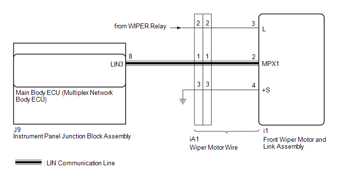
The main body ECU (multiplex network body ECU) and windshield wiper motor and link assembly communicate via LIN communication. The main body ECU (multiplex network body ECU) stores this DTC if communication becomes abnormal.
| DTC No. | Detection Item | DTC Detection Condition | Trouble Area | Memory | DTC Output from |
|---|---|---|---|---|---|
| B1245 | Lost Communication with Wiper ECU LIN | When the battery voltage is 9.5 V or more, a communication malfunction between the main body ECU (multiplex network body ECU) and windshield wiper motor and link assembly (wiper ECU) is detected for 10 seconds or more |
| ○ | Main body ECU (multiplex network body ECU) |
WIRING DIAGRAM
PROCEDURE
| 1. | CLEAR DTC |
(a) Clear the DTCs.
Click here .gif)
|
.gif)
| 2. | CHECK FOR DTC |
(a) Turn the engine switch on (IG).
(b) Check for DTCs.
Click here
| Result | Proceed to |
|---|---|
| DTC B1245 is not output. | A |
| DTC B1245 is output. | B |
| A | .gif) | USE SIMULATION METHOD TO CHECK |
|
| 3. | CHECK HARNESS AND CONNECTOR (MAIN BODY ECU (MULTIPLEX NETWORK BODY ECU) - FRONT WIPER MOTOR AND LINK ASSEMBLY) |
(a) Disconnect the J9 main body ECU (multiplex network body ECU) connector.
(b) Disconnect the i1 front wiper motor and link assembly connector.
(c) Measure the resistance according to the value(s) in the table below.
Standard Resistance:
| Tester Connection | Condition | Specified Condition |
|---|---|---|
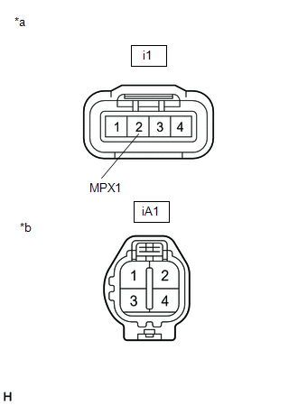
| J9-8 (LIN3) - i1-2 (MPX1) | Always | Below 1 Ω |
| J9-8 (LIN3) or i1-2 (MPX1) - Body ground | Always | 10 kΩ or higher |
| NG | | GO TO STEP 9 |
|
| 4. | CHECK HARNESS AND CONNECTOR (FRONT WIPER MOTOR AND LINK ASSEMBLY - POWER SOURCE) |
(a) Measure the voltage according to the value(s) in the table below.
Standard Voltage:
| Tester Connection | Condition | Specified Condition |
|---|---|---|
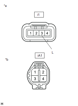
| i1-3 (L) - Body ground | Engine switch off | Below 1 V |
| Engine switch on (IG) | 11 to 14 V |
| NG | | GO TO STEP 8 |
|
| 5. | CHECK HARNESS AND CONNECTOR (FRONT WIPER MOTOR AND LINK ASSEMBLY - BODY GROUND) |
(a) Measure the resistance according to the value(s) in the table below.
Standard Resistance:
| Tester Connection | Condition | Specified Condition |
|---|---|---|
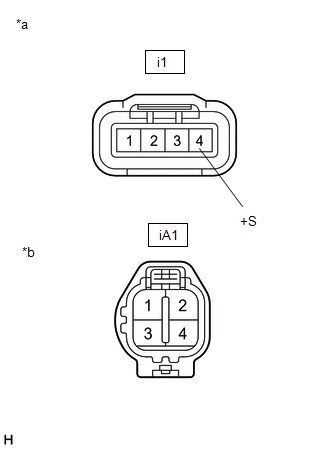
| i1-4 (+S) - Body ground | Always | Below 1 Ω |
| NG | | GO TO STEP 7 |
|
| 6. | REPLACE FRONT WIPER MOTOR AND LINK ASSEMBLY |
(a) Replace the front wiper motor and link assembly with a new or known good one.
Click here
(b) Turn the engine switch on (IG).
(c) Check for DTCs.
Click here
| Result | Proceed to |
|---|---|
| DTC B1245 is not output. | A |
| DTC B1245 is output. | B |
| A | | END |
| B | | REPLACE MAIN BODY ECU (MULTIPLEX NETWORK BODY ECU) |
| 7. | CHECK WIPER MOTOR WIRE |
(a) Remove the wiper motor wire.
Click here
| (b) Measure the resistance according to the value(s) in the table below. Standard Resistance:
|
|
| OK | | REPAIR OR REPLACE HARNESS OR CONNECTOR |
| NG | | REPLACE WIPER MOTOR WIRE |
| 8. | CHECK WIPER MOTOR WIRE |
(a) Remove the wiper motor wire.
Click here
| (b) Measure the resistance according to the value(s) in the table below. Standard Resistance:
|
|
| OK | | REPAIR OR REPLACE HARNESS OR CONNECTOR |
| NG | | REPLACE WIPER MOTOR WIRE |
| 9. | CHECK WIPER MOTOR WIRE |
(a) Remove the wiper motor wire.
Click here
| (b) Measure the resistance according to the value(s) in the table below. Standard Resistance:
|
|
| OK | | REPAIR OR REPLACE HARNESS OR CONNECTOR |
| NG | | REPLACE WIPER MOTOR WIRE |
 Diagnostic Trouble Code Chart
DIAGNOSTIC TROUBLE CODE CHART Wiper and Washer System DTC No. Detection Item DTC Detection Condition Link B1245 Lost Communication with Wiper ECU LIN When the battery voltage is 9.5 V ...
 Lost Communication with Combination Switch ECU (B1278)
DESCRIPTION The main body ECU (multiplex network body ECU) and windshield wiper switch assembly communicate via LIN communication. The main body ECU (multiplex network body ECU) stores this DTC if com ...
Other materials:
Lexus RX (RX 350L, RX450h) 2016-2026 Repair Manual > Rear Seat Cushion Heater (for 60/40 Split Seat Type Rh Side): Installation
INSTALLATION CAUTION / NOTICE / HINT CAUTION: Wear protective gloves. Sharp areas on the seat frame may injure your hands. PROCEDURE 1. INSTALL SEAT HEATER ASSEMBLY (w/o Rear No. 2 Seat) (a) Install the seat heater assembly to the separate type rear seat cushion cover with 14 new tag pins. 2. INSTAL ...
Lexus RX (RX 350L, RX450h) 2016-2026 Repair Manual > Transmission Control Cable: Installation
INSTALLATION PROCEDURE 1. INSTALL TRANSMISSION CONTROL CABLE ASSEMBLY (for TMC Made) NOTICE: Before installing the transmission control cable assembly, check that the park/neutral position switch assembly and the shift lever are in neutral. (a) Pass the transmission control cable assembly from the c ...
Lexus RX (RX 350L, RX450h) 2016-{YEAR} Owners Manual
- For your information
- Pictorial index
- For safety and security
- Instrument cluster
- Operation of each component
- Driving
- Lexus Display Audio system
- Interior features
- Maintenance and care
- When trouble arises
- Vehicle specifications
- For owners
Lexus RX (RX 350L, RX450h) 2016-{YEAR} Repair Manual

0.0138