Lexus RX (RX 350L, RX450h) 2016-2026 Repair Manual: Lost Communication with Combination Switch ECU (B1278)
DESCRIPTION
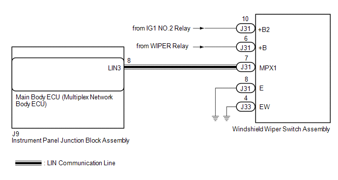
The main body ECU (multiplex network body ECU) and windshield wiper switch assembly communicate via LIN communication. The main body ECU (multiplex network body ECU) stores this DTC if communication becomes abnormal.
| DTC No. | Detection Item | DTC Detection Condition | Trouble Area | Memory | DTC Output from |
|---|---|---|---|---|---|
| B1278 | Lost Communication with Combination Switch ECU | When the battery voltage is 9.5 V or more, a communication malfunction between the main body ECU (multiplex network body ECU) and windshield wiper switch assembly is detected for 10 seconds or more. |
| ○ | Main body ECU (multiplex network body ECU) |
WIRING DIAGRAM
PROCEDURE
| 1. | CLEAR DTC |
(a) Clear the DTCs.
Click here .gif)
|
.gif)
| 2. | CHECK FOR DTC |
(a) Turn the engine switch on (IG).
(b) Check for DTCs.
Click here
| Result | Proceed to |
|---|---|
| DTC B1278 is not output. | A |
| DTC B1278 is output. | B |
| A | .gif) | USE SIMULATION METHOD TO CHECK |
|
| 3. | CHECK HARNESS AND CONNECTOR (MAIN BODY ECU (MULTIPLEX NETWORK BODY ECU) - WINDSHIELD WIPER SWITCH ASSEMBLY) |
(a) Disconnect the J9 main body ECU (multiplex network body ECU) connector.
(b) Disconnect the J31 windshield wiper switch assembly connector.
(c) Measure the resistance according to the value(s) in the table below.
Standard Resistance:
| Tester Connection | Condition | Specified Condition |
|---|---|---|
| J9-8 (LIN3) - J31-7 (MPX1) | Always | Below 1 Ω |
| J9-8 (LIN3) or J31-7 (MPX1) - Body ground | Always | 10 kΩ or higher |
| NG | | REPAIR OR REPLACE HARNESS OR CONNECTOR |
|
| 4. | CHECK HARNESS AND CONNECTOR (FRONT WIPER MOTOR AND LINK ASSEMBLY - POWER SOURCE) |
(a) Measure the voltage according to the value(s) in the table below.
Standard Voltage:
| Tester Connection | Condition | Specified Condition |
|---|---|---|
| J31-10 (+B2) - Body ground | Engine switch off | Below 1 V |
| Engine switch on (IG) | 11 to 14 V | |
| J31-6 (+B) - Body ground | Engine switch off | Below 1 V |
| Engine switch on (IG) | 11 to 14 V |
| NG | | REPAIR OR REPLACE HARNESS OR CONNECTOR |
|
| 5. | CHECK HARNESS AND CONNECTOR (WINDSHIELD WIPER SWITCH ASSEMBLY - BODY GROUND) |
(a) Disconnect the J33 windshield wiper switch assembly connector.
(b) Measure the resistance according to the value(s) in the table below.
Standard Resistance:
| Tester Connection | Condition | Specified Condition |
|---|---|---|
| J31-8 (E) - Body ground | Always | Below 1 Ω |
| J33-4 (EW) - Body ground | Always | Below 1 Ω |
| NG | | REPAIR OR REPLACE HARNESS OR CONNECTOR |
|
| 6. | REPLACE WINDSHIELD WIPER SWITCH ASSEMBLY |
(a) Replace the windshield wiper switch assembly with a new or known good one.
Click here
(b) Turn the engine switch on (IG).
(c) Check for DTCs.
Click here
| Result | Proceed to |
|---|---|
| DTC B1278 is not output. | A |
| DTC B1278 is output. | B |
| A | | END |
| B | | REPLACE MAIN BODY ECU (MULTIPLEX NETWORK BODY ECU) |
 Lost Communication with Wiper ECU LIN (B1245)
DESCRIPTION The main body ECU (multiplex network body ECU) and windshield wiper motor and link assembly communicate via LIN communication. The main body ECU (multiplex network body ECU) stores this DT ...
 Lost Communication with Humidity/Rain Sensor LIN (B1279)
DESCRIPTION The main body ECU (multiplex network body ECU) and rain sensor communicate via LIN communication. The main body ECU (multiplex network body ECU) stores this DTC if communication becomes ab ...
Other materials:
Lexus RX (RX 350L, RX450h) 2016-2026 Repair Manual > Lighting (int): Door Courtesy Light Bulb
ReplacementREPLACEMENT PROCEDURE 1. REMOVE COURTESY LIGHT ASSEMBLY (for Front Door) (a) Using a screwdriver with its tip wrapped with protective tape, disengage the claw. *A for LH Side *B for RH Side *a Protective Tape (b) Disconnect the connector to remove th ...
Lexus RX (RX 350L, RX450h) 2016-2026 Repair Manual > Lighting (int): Scuff Plate Light
ComponentsCOMPONENTS ILLUSTRATION *1 FRONT DOOR SCUFF PLATE LH *2 FRONT DOOR SCUFF PLATE RH RemovalREMOVAL PROCEDURE 1. REMOVE FRONT DOOR SCUFF PLATE LH Click here 2. REMOVE FRONT DOOR SCUFF PLATE RH HINT: Use the same procedure as for the LH side. InspectionINSPECTION PROCEDURE 1. ...
Lexus RX (RX 350L, RX450h) 2016-{YEAR} Owners Manual
- For your information
- Pictorial index
- For safety and security
- Instrument cluster
- Operation of each component
- Driving
- Lexus Display Audio system
- Interior features
- Maintenance and care
- When trouble arises
- Vehicle specifications
- For owners
Lexus RX (RX 350L, RX450h) 2016-{YEAR} Repair Manual

0.1281