Lexus RX (RX 350L, RX450h) 2016-2026 Repair Manual: Lost Communication with Humidity/Rain Sensor LIN (B1279)
DESCRIPTION
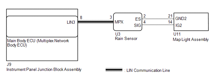
The main body ECU (multiplex network body ECU) and rain sensor communicate via LIN communication. The main body ECU (multiplex network body ECU) stores this DTC if communication becomes abnormal.
| DTC No. | Detection Item | DTC Detection Condition | Trouble Area | Memory | DTC Output from |
|---|---|---|---|---|---|
| B1279 | Lost Communication with Humidity/Rain Sensor LIN | When the battery voltage is 9.5 V or more, a communication malfunction between the main body ECU (multiplex network body ECU) and rain sensor is detected for 10 seconds or more. |
| ○ | Main body ECU (multiplex network body ECU) |
WIRING DIAGRAM
PROCEDURE
| 1. | CLEAR DTC |
(a) Clear the DTCs.
Click here .gif)
|
.gif)
| 2. | CHECK FOR DTC |
(a) Turn the engine switch on (IG).
(b) Check for DTCs.
Click here
| Result | Proceed to |
|---|---|
| DTC B1278 is not output. | A |
| DTC B1278 is output. | B |
| A | .gif) | USE SIMULATION METHOD TO CHECK |
|
| 3. | CHECK HARNESS AND CONNECTOR (MAIN BODY ECU (MULTIPLEX NETWORK BODY ECU) - RAIN SENSOR) |
(a) Disconnect the J9 main body ECU (multiplex network body ECU) connector.
(b) Disconnect the U3 rain sensor connector.
(c) Measure the resistance according to the value(s) in the table below.
Standard Resistance:
| Tester Connection | Condition | Specified Condition |
|---|---|---|
| J9-8 (LIN3) - U3-3 (MPX) | Always | Below 1 Ω |
| J9-8 (LIN3) or U3-3 (MPX) - Body ground | Always | 10 kΩ or higher |
| NG | | REPAIR OR REPLACE HARNESS OR CONNECTOR |
|
| 4. | CHECK HARNESS AND CONNECTOR (FRONT WIPER MOTOR AND LINK ASSEMBLY - POWER SOURCE) |
(a) Measure the voltage according to the value(s) in the table below.
Standard Voltage:
| Tester Connection | Condition | Specified Condition |
|---|---|---|
| U3-4 (SIG) - U3-2 (ES) | Engine switch off | Below 1 V |
| Engine switch on (IG) | 11 to 14 V |
| NG | | GO TO STEP 6 |
|
| 5. | REPLACE RAIN SENSOR |
(a) Replace the rain sensor with a new or known good one.
Click here
(b) Turn the engine switch on (IG).
(c) Check for DTCs.
Click here
| Result | Proceed to |
|---|---|
| DTC B1279 is not output. | A |
| DTC B1279 is output. | B |
| A | | END |
| B | | REPLACE MAIN BODY ECU (MULTIPLEX NETWORK BODY ECU) |
| 6. | INSPECT MAP LIGHT ASSEMBLY |
(a) Remove the map light assembly.
Click here
(b) Inspect the map light assembly.
Click here
| OK | | REPAIR OR REPLACE HARNESS OR CONNECTOR |
| NG | | REPLACE MAP LIGHT ASSEMBLY |
 Lost Communication with Combination Switch ECU (B1278)
DESCRIPTION The main body ECU (multiplex network body ECU) and windshield wiper switch assembly communicate via LIN communication. The main body ECU (multiplex network body ECU) stores this DTC if com ...
 ECU Malfunction (B1370)
DESCRIPTION This DTC is stored when the front wiper motor and link assembly (wiper ECU) detects an internal malfunction. DTC No. Detection Item DTC Detection Condition Trouble Area Memory ...
Other materials:
Lexus RX (RX 350L, RX450h) 2016-2026 Repair Manual > Quarter Trim Speaker (w/o Rear No. 2 Seat): Inspection
INSPECTION PROCEDURE 1. INSPECT QUARTER SIDE SPEAKER ASSEMBLY (a) With the speaker installed, check that there is no looseness or other abnormalities. (b) Check that there is no foreign matter in the speaker, no tears on the speaker cone or other abnormalities. (c) Measure the resistance of the s ...
Lexus RX (RX 350L, RX450h) 2016-2026 Repair Manual > Theft Deterrent System: Problem Symptoms Table
PROBLEM SYMPTOMS TABLE NOTICE: Before replacing the main body ECU (multiplex network body ECU), refer to Registration. Click here HINT:
Troubleshooting of the theft deterrent system is based on the premise that the power door lock control system and the wireless door lock control system are o ...
Lexus RX (RX 350L, RX450h) 2016-{YEAR} Owners Manual
- For your information
- Pictorial index
- For safety and security
- Instrument cluster
- Operation of each component
- Driving
- Lexus Display Audio system
- Interior features
- Maintenance and care
- When trouble arises
- Vehicle specifications
- For owners
Lexus RX (RX 350L, RX450h) 2016-{YEAR} Repair Manual

0.0086