Lexus RX (RX 350L, RX450h) 2016-2026 Repair Manual: Speaker Output Short (B15C3)
DESCRIPTION
This DTC is stored when a malfunction occurs in the speakers.
| DTC No. | Detection Item | DTC Detection Condition | Trouble Area |
|---|---|---|---|
| B15C3 | Speaker Output Short | A short is detected in the speaker output circuit. |
|
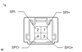
- *: w/ Manual (SOS) Switch
WIRING DIAGRAM
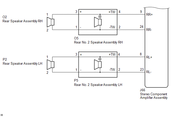
for 9 Speakers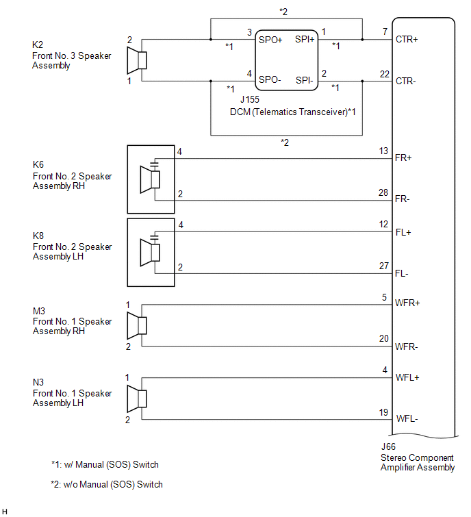
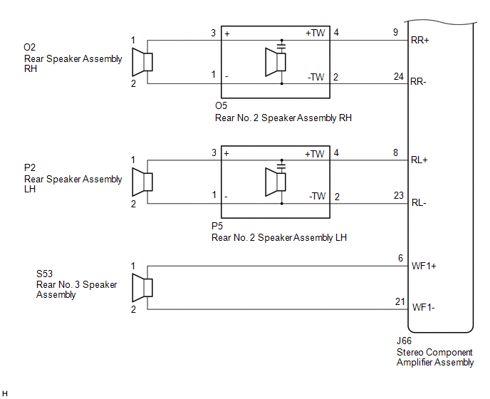
 for 12 Speakers
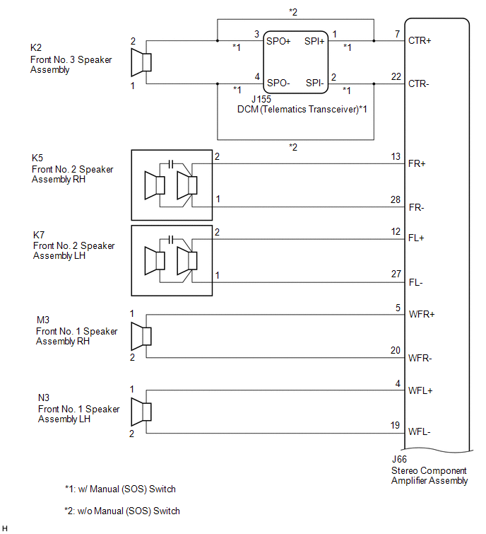
CAUTION / NOTICE / HINT
NOTICE:
-
Depending on the parts that are replaced during vehicle inspection or maintenance, performing initialization, registration or calibration may be needed. Refer to Precaution for Audio and Visual System.
Click here
.gif)
-
Before replacing the DCM (telematics transceiver), refer to Registration.
Click here
PROCEDURE
| 1. | CHECK MODEL |
(a) Choose the model to be inspected.
| Result | Proceed to |
|---|---|
| for 9 Speakers (w/ Manual (SOS) Switch) | A |
| for 9 Speakers (w/o Manual (SOS) Switch) | B |
| for 12 Speakers (w/ Manual (SOS) Switch) | C |
| for 12 Speakers (w/o Manual (SOS) Switch) | D |
| B | .gif) | GO TO STEP 5 |
| C | | GO TO STEP 12 |
| D | | GO TO STEP 15 |
|
.gif)
| 2. | CHECK HARNESS AND CONNECTOR (STEREO COMPONENT AMPLIFIER ASSEMBLY, DCM (TELEMATICS TRANSCEIVER) OR SPEAKERS- BODY GROUND) |
(a) Disconnect the J66 stereo component amplifier assembly connector.
(b) Disconnect the J155 DCM (telematics transceiver) connector.
(c) Disconnect the K6 and K8 front No. 2 speaker assembly connectors.
(d) Disconnect the M3 and N3 front No. 1 speaker assembly connectors.
(e) Disconnect the O5 and P5 rear No. 2 speaker assembly connectors.
(f) Measure the resistance according to the value(s) in the table below.
Standard Resistance:
| Tester Connection | Condition | Specified Condition |
|---|---|---|
| J66-7 (CTR+) or J155-1 (SPI+) - Body ground | Always | 10 kΩ or higher |
| J66-22 (CTR-) or J155-2 (SPI-) - Body ground | Always | 10 kΩ or higher |
| J66-13 (FR+) or K6-4 - Body ground | Always | 10 kΩ or higher |
| J66-28 (FR-) or K6-2 - Body ground | Always | 10 kΩ or higher |
| J66-12 (FL+) or K8-4 - Body ground | Always | 10 kΩ or higher |
| J66-27 (FL-) or K8-2 - Body ground | Always | 10 kΩ or higher |
| J66-5 (WFR+) or M3-1 - Body ground | Always | 10 kΩ or higher |
| J66-20 (WFR-) or M3-2 - Body ground | Always | 10 kΩ or higher |
| J66-4 (WFL+) or N3-1 - Body ground | Always | 10 kΩ or higher |
| J66-19 (WFL-) or N3-2 - Body ground | Always | 10 kΩ or higher |
| J66-9 (RR+) or O5-4 (+TW) - Body ground | Always | 10 kΩ or higher |
| J66-24 (RR-) or O5-2 (-TW) - Body ground | Always | 10 kΩ or higher |
| J66-8 (RL+) or P5-4 (+TW) - Body ground | Always | 10 kΩ or higher |
| J66-23 (RL-) or P5-2 (-TW) - Body ground | Always | 10 kΩ or higher |
| NG | | REPAIR OR REPLACE HARNESS OR CONNECTOR |
|
| 3. | CHECK HARNESS AND CONNECTOR (DCM (TELEMATICS TRANSCEIVER) OR NO. 3 FRONT SPEAKER ASSEMBLY- BODY GROUND) |
(a) Disconnect the J155 DCM (telematics transceiver) connector.
(b) Disconnect the K2 front No. 3 speaker assembly connector.
(c) Measure the resistance according to the value(s) in the table below.
Standard Resistance:
| Tester Connection | Condition | Specified Condition |
|---|---|---|
| K2-2 or J155-3 (SPO+) - Body ground | Always | 10 kΩ or higher |
| K2-1 or J155-4 (SPO-) - Body ground | Always | 10 kΩ or higher |
| NG | | REPAIR OR REPLACE HARNESS OR CONNECTOR |
|
| 4. | INSPECT DCM (TELEMATICS TRANSCEIVER) |
(a) Remove the DCM (telematics transceiver).
Click here
| (b) Measure the resistance according to the value(s) in the table below. Standard Resistance:
|
|
| OK | | GO TO STEP 6 |
| NG | | REPLACE DCM (TELEMATICS TRANSCEIVER) |
| 5. | CHECK HARNESS AND CONNECTOR (STEREO COMPONENT AMPLIFIER ASSEMBLY OR SPEAKERS - BODY GROUND) |
(a) Disconnect the J66 stereo component amplifier assembly connector.
(b) Disconnect the K2 front No. 3 speaker assembly connector.
(c) Disconnect the K6 and K8 front No. 2 speaker assembly connectors.
(d) Disconnect the M3 and N3 front No. 1 speaker assembly connectors.
(e) Disconnect the O5 and P5 rear No. 2 speaker assembly connectors.
(f) Measure the resistance according to the value(s) in the table below.
Standard Resistance:
| Tester Connection | Condition | Specified Condition |
|---|---|---|
| J66-7 (CTR+) or K2-2 - Body ground | Always | 10 kΩ or higher |
| J66-22 (CTR-) or K2-1 - Body ground | Always | 10 kΩ or higher |
| J66-13 (FR+) or K6-4 - Body ground | Always | 10 kΩ or higher |
| J66-28 (FR-) or K6-2 - Body ground | Always | 10 kΩ or higher |
| J66-12 (FL+) or K8-4 - Body ground | Always | 10 kΩ or higher |
| J66-27 (FL-) or K8-2 - Body ground | Always | 10 kΩ or higher |
| J66-5 (WFR+) or M3-1 - Body ground | Always | 10 kΩ or higher |
| J66-20 (WFR-) or M3-2 - Body ground | Always | 10 kΩ or higher |
| J66-4 (WFL+) or N3-1 - Body ground | Always | 10 kΩ or higher |
| J66-19 (WFL-) or N3-2 - Body ground | Always | 10 kΩ or higher |
| J66-9 (RR+) or O5-4 (+TW) - Body ground | Always | 10 kΩ or higher |
| J66-24 (RR-) or O5-2 (-TW) - Body ground | Always | 10 kΩ or higher |
| J66-8 (RL+) or P5-4 (+TW) - Body ground | Always | 10 kΩ or higher |
| J66-23 (RL-) or P5-2 (-TW) - Body ground | Always | 10 kΩ or higher |
| NG | | REPAIR OR REPLACE HARNESS OR CONNECTOR |
|
| 6. | CHECK HARNESS AND CONNECTOR (REAR SPEAKER ASSEMBLY OR REAR NO. 2 SPEAKER ASSEMBLY - BODY GROUND) |
(a) Disconnect the O2 and P2 rear speaker assembly connectors.
(b) Disconnect the O5 and P5 rear No. 2 speaker assembly connectors.
(c) Measure the resistance according to the value(s) in the table below.
Standard Resistance:
| Tester Connection | Condition | Specified Condition |
|---|---|---|
| O2-1 or O5-3 (+) - Body ground | Always | 10 kΩ or higher |
| O2-2 or O5-1 (-) - Body ground | Always | 10 kΩ or higher |
| P2-1 or P5-3 (+) - Body ground | Always | 10 kΩ or higher |
| P2-2 or P5-1 (-) - Body ground | Always | 10 kΩ or higher |
| NG | | REPAIR OR REPLACE HARNESS OR CONNECTOR |
|
| 7. | INSPECT FRONT NO. 3 SPEAKER ASSEMBLY |
(a) Remove the front No. 3 speaker assembly.
Click here
(b) Inspect the front No. 3 speaker assembly.
Click here
| NG | | REPLACE FRONT NO. 3 SPEAKER ASSEMBLY |
|
| 8. | INSPECT FRONT NO. 1 SPEAKER ASSEMBLY |
(a) Remove the front No. 1 speaker assembly.
Click here
(b) Inspect the front No. 1 speaker assembly.
Click here
| NG | | REPLACE FRONT NO. 1 SPEAKER ASSEMBLY |
|
| 9. | INSPECT REAR SPEAKER ASSEMBLY |
(a) Remove the rear speaker assembly.
Click here
(b) Inspect the rear speaker assembly.
Click here
| NG | | REPLACE REAR SPEAKER ASSEMBLY |
|
| 10. | INSPECT FRONT NO. 2 SPEAKER ASSEMBLY |
(a) Remove the front No. 2 speaker assembly.
Click here
(b) Inspect the front No. 2 speaker assembly.
Click here
(c) Clear the DTCs.
Body Electrical > Navigation System > Clear DTCs(d) Recheck for DTCs and check that no DTCs are output.
Body Electrical > Navigation System > Trouble CodesOK:
No DTCs are output.
| OK | | END |
|
| 11. | REPLACE REAR NO. 2 SPEAKER ASSEMBLY |
(a) Remove the rear No. 2 speaker assembly.
Click here
(b) Inspect the rear No. 2 speaker assembly.
Click here
(c) Clear the DTCs.
Body Electrical > Navigation System > Clear DTCs(d) Recheck for DTCs and check that no DTCs are output.
Body Electrical > Navigation System > Trouble CodesOK:
No DTCs are output.
| OK | | END |
| NG | | REPLACE STEREO COMPONENT AMPLIFIER ASSEMBLY |
| 12. | CHECK HARNESS AND CONNECTOR (STEREO COMPONENT AMPLIFIER ASSEMBLY, DCM (TELEMATICS TRANSCEIVER) OR SPEAKERS - BODY GROUND) |
(a) Disconnect the J66 stereo component amplifier assembly connector.
(b) Disconnect the J155 DCM (telematics transceiver) connector.
(c) Disconnect the K5 and K7 front No. 2 speaker assembly connectors.
(d) Disconnect the M3 and N3 front No. 1 speaker assembly connectors.
(e) Disconnect the O5 and P5 rear No. 2 speaker assembly connectors.
(f) Disconnect the S53 rear No. 3 speaker assembly connector.
(g) Measure the resistance according to the value(s) in the table below.
Standard Resistance:
| Tester Connection | Condition | Specified Condition |
|---|---|---|
| J66-7 (CTR+) or J155-1 (SPI+) - Body ground | Always | 10 kΩ or higher |
| J66-22 (CTR-) or J155-2 (SPI-) - Body ground | Always | 10 kΩ or higher |
| J66-13 (FR+) or K5-2 - Body ground | Always | 10 kΩ or higher |
| J66-28 (FR-) or K5-1 - Body ground | Always | 10 kΩ or higher |
| J66-12 (FL+) or K7-2 - Body ground | Always | 10 kΩ or higher |
| J66-27 (FL-) or K7-1 - Body ground | Always | 10 kΩ or higher |
| J66-5 (WFR+) or M3-1 - Body ground | Always | 10 kΩ or higher |
| J66-20 (WFR-) or M3-2 - Body ground | Always | 10 kΩ or higher |
| J66-4 (WFL+) or N3-1 - Body ground | Always | 10 kΩ or higher |
| J66-19 (WFL-) or N3-2 - Body ground | Always | 10 kΩ or higher |
| J66-9 (RR+) or O5-4 (+TW) - Body ground | Always | 10 kΩ or higher |
| J66-24 (RR-) or O5-2 (-TW) - Body ground | Always | 10 kΩ or higher |
| J66-8 (RL+) or P5-4 (+TW) - Body ground | Always | 10 kΩ or higher |
| J66-23 (RL-) or P5-2 (-TW) - Body ground | Always | 10 kΩ or higher |
| J66-6 (WF1+) or S53-1 - Body ground | Always | 10 kΩ or higher |
| J66-21 (WF1-) or S53-2 - Body ground | Always | 10 kΩ or higher |
| NG | | REPAIR OR REPLACE HARNESS OR CONNECTOR |
|
| 13. | CHECK HARNESS AND CONNECTOR (DCM (TELEMATICS TRANSCEIVER) OR FRONT NO. 3 SPEAKER ASSEMBLY- BODY GROUND) |
(a) Disconnect the J155 DCM (telematics transceiver) connector.
(b) Disconnect the K2 front No. 3 speaker assembly connector.
(c) Measure the resistance according to the value(s) in the table below.
Standard Resistance:
| Tester Connection | Condition | Specified Condition |
|---|---|---|
| K2-2 or J155-3 (SPO+) - Body ground | Always | 10 kΩ or higher |
| K2-1 or J155-4 (SPO-) - Body ground | Always | 10 kΩ or higher |
| NG | | REPAIR OR REPLACE HARNESS OR CONNECTOR |
|
| 14. | INSPECT DCM (TELEMATICS TRANSCEIVER) |
(a) Remove the DCM (telematics transceiver).
Click here
| (b) Measure the resistance according to the value(s) in the table below. Standard Resistance:
|
|
| OK | | GO TO STEP 16 |
| NG | | REPLACE DCM (TELEMATICS TRANSCEIVER) |
| 15. | CHECK HARNESS AND CONNECTOR (STEREO COMPONENT AMPLIFIER ASSEMBLY OR SPEAKERS - BODY GROUND) |
(a) Disconnect the J66 stereo component amplifier assembly connector.
(b) Disconnect the K2 front No. 3 speaker assembly connector.
(c) Disconnect the K5 and K7 front No. 2 speaker assembly connectors.
(d) Disconnect the M3 and N3 front No. 1 speaker assembly connectors.
(e) Disconnect the O5 and P5 rear No. 2 speaker assembly connectors.
(f) Disconnect the S53 rear No. 3 speaker assembly connector.
(g) Measure the resistance according to the value(s) in the table below.
Standard Resistance:
| Tester Connection | Condition | Specified Condition |
|---|---|---|
| J66-7 (CTR+) or K2-2 - Body ground | Always | 10 kΩ or higher |
| J66-22 (CTR-) or K2-1 - Body ground | Always | 10 kΩ or higher |
| J66-13 (FR+) or K5-2 - Body ground | Always | 10 kΩ or higher |
| J66-28 (FR-) or K5-1 - Body ground | Always | 10 kΩ or higher |
| J66-12 (FL+) or K7-2 - Body ground | Always | 10 kΩ or higher |
| J66-27 (FL-) or K7-1 - Body ground | Always | 10 kΩ or higher |
| J66-5 (WFR+) or M3-1 - Body ground | Always | 10 kΩ or higher |
| J66-20 (WFR-) or M3-2 - Body ground | Always | 10 kΩ or higher |
| J66-4 (WFL+) or N3-1 - Body ground | Always | 10 kΩ or higher |
| J66-19 (WFL-) or N3-2 - Body ground | Always | 10 kΩ or higher |
| J66-9 (RR+) or O5-4 (+TW) - Body ground | Always | 10 kΩ or higher |
| J66-24 (RR-) or O5-2 (-TW) - Body ground | Always | 10 kΩ or higher |
| J66-8 (RL+) or P5-4 (+TW) - Body ground | Always | 10 kΩ or higher |
| J66-23 (RL-) or P5-2 (-TW) - Body ground | Always | 10 kΩ or higher |
| J66-6 (WF1+) or S53-1 - Body ground | Always | 10 kΩ or higher |
| J66-21 (WF1-) or S53-2 - Body ground | Always | 10 kΩ or higher |
| NG | | REPAIR OR REPLACE HARNESS OR CONNECTOR |
|
| 16. | CHECK HARNESS AND CONNECTOR (REAR SPEAKER ASSEMBLY OR REAR NO. 2 SPEAKER ASSEMBLY - BODY GROUND) |
(a) Disconnect the O2 and P2 rear speaker assembly connectors.
(b) Disconnect the O5 and P5 rear No. 2 speaker assembly connectors.
(c) Measure the resistance according to the value(s) in the table below.
Standard Resistance:
| Tester Connection | Condition | Specified Condition |
|---|---|---|
| O2-1 or O5-3 (+) - Body ground | Always | 10 kΩ or higher |
| O2-2 or O5-1 (-) - Body ground | Always | 10 kΩ or higher |
| P2-1 or P5-3 (+) - Body ground | Always | 10 kΩ or higher |
| P2-2 or P5-1 (-) - Body ground | Always | 10 kΩ or higher |
| NG | | REPAIR OR REPLACE HARNESS OR CONNECTOR |
|
| 17. | INSPECT FRONT NO. 3 SPEAKER ASSEMBLY |
(a) Remove the front No. 3 speaker assembly.
Click here
(b) Inspect the front No. 3 speaker assembly.
Click here
| NG | | REPLACE FRONT NO. 3 SPEAKER ASSEMBLY |
|
| 18. | INSPECT FRONT NO. 1 SPEAKER ASSEMBLY |
(a) Remove the front No. 1 speaker assembly.
Click here
(b) Inspect the front No. 1 speaker assembly.
Click here
| NG | | REPLACE FRONT NO. 1 SPEAKER ASSEMBLY |
|
| 19. | INSPECT REAR SPEAKER ASSEMBLY |
(a) Remove the rear speaker assembly.
Click here
(b) Inspect the rear speaker assembly.
Click here
| NG | | REPLACE REAR SPEAKER ASSEMBLY |
|
| 20. | INSPECT REAR NO. 3 SPEAKER ASSEMBLY |
(a) Remove the rear No. 3 speaker assembly.
w/o Rear No. 2 Seat: Click here
w/ Rear No. 2 Seat: Click here
(b) Inspect the rear No. 3 speaker assembly.
w/o Rear No. 2 Seat: Click here
w/ Rear No. 2 Seat: Click here
| NG | | REPLACE REAR NO. 3 SPEAKER ASSEMBLY |
|
| 21. | INSPECT REAR NO. 2 SPEAKER ASSEMBLY |
(a) Remove the rear No. 2 speaker assembly.
Click here
(b) Inspect the rear No. 2 speaker assembly.
Click here
(c) Clear the DTCs.
Body Electrical > Navigation System > Clear DTCs(d) Recheck for DTCs and check that no DTCs are output.
Body Electrical > Navigation System > Trouble CodesOK:
No DTCs are output.
| OK | | END |
|
| 22. | REPLACE FRONT NO. 2 SPEAKER ASSEMBLY |
(a) Remove the front No. 2 speaker assembly.
Click here
(b) Inspect the front No. 2 speaker assembly.
Click here
(c) Clear the DTCs.
Body Electrical > Navigation System > Clear DTCs(d) Recheck for DTCs and check that no DTCs are output.
Body Electrical > Navigation System > Trouble CodesOK:
No DTCs are output.
| OK | | END |
| NG | | REPLACE STEREO COMPONENT AMPLIFIER ASSEMBLY |
 GPS Antenna Connection Malfunction(short) (B15C0,B15C1)
DESCRIPTION These DTCs are stored when a malfunction occurs in the navigation antenna assembly. DTC No. Detection Item DTC Detection Condition Trouble Area B15C0 GPS Antenna Connection ...
 Stereo Component Amplifier Disconnected (B15D3)
DESCRIPTION The radio receiver assembly and stereo component amplifier assembly are connected by AVC-LAN communication lines. This DTC is stored when an AVC-LAN communication error occurs between the ...
Other materials:
Lexus RX (RX 350L, RX450h) 2016-2026 Repair Manual > Rear Combination Light Assembly (w/ Rear No. 2 Seat): Removal
REMOVAL CAUTION / NOTICE / HINT HINT:
Use the same procedure for the RH side and LH side.
The following procedure is for the LH side.
PROCEDURE 1. REMOVE REAR NO. 2 SEAT ASSEMBLY Click here 2. REMOVE REAR DOOR SCUFF PLATE Click here 3. REMOVE REAR DOOR INSIDE SCUFF PLATE Click here 4. ...
Lexus RX (RX 350L, RX450h) 2016-2026 Repair Manual > Camshaft Oil Control Solenoid (for Bank 1): Installation
INSTALLATION CAUTION / NOTICE / HINT CAUTION:
The engine assembly with transaxle is very heavy. Be sure to follow the procedure described in the repair manual, or the engine lifter may suddenly drop or the engine assembly with transaxle may fall off the engine lifter.
To prevent burns, do not t ...
Lexus RX (RX 350L, RX450h) 2016-{YEAR} Owners Manual
- For your information
- Pictorial index
- For safety and security
- Instrument cluster
- Operation of each component
- Driving
- Lexus Display Audio system
- Interior features
- Maintenance and care
- When trouble arises
- Vehicle specifications
- For owners
Lexus RX (RX 350L, RX450h) 2016-{YEAR} Repair Manual

0.0138