Lexus RX (RX 350L, RX450h) 2016-2026 Repair Manual: Stereo Component Amplifier Disconnected (B15D3)
DESCRIPTION
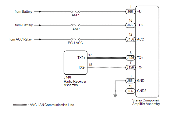
The radio receiver assembly and stereo component amplifier assembly are connected by AVC-LAN communication lines.
This DTC is stored when an AVC-LAN communication error occurs between the radio receiver assembly and stereo component amplifier assembly.
| DTC No. | Detection Item | DTC Detection Condition | Trouble Area |
|---|---|---|---|
| B15D3 | Stereo Component Amplifier Disconnected | A device that is listed in the AVC-LAN connected device record of the master unit is missing |
|
HINT:
The radio receiver assembly is the master unit.
WIRING DIAGRAM
CAUTION / NOTICE / HINT
NOTICE:
-
Depending on the parts that are replaced during vehicle inspection or maintenance, performing initialization, registration or calibration may be needed. Refer to Precaution for Audio and Visual System.
Click here
.gif)
- Inspect the fuses for circuits related to this system before performing the following procedure.
PROCEDURE
| 1. | CHECK DTC |
(a) If DTC B15C3 is output, perform troubleshooting for DTC B15C3 first.
| Result | Proceed to |
|---|---|
| DTC B15C3 is not output. | A |
| DTC B15C3 is output. | B |
| B |  | GO TO DTC B15C3 |
|

| 2. | CHECK OPTIONAL COMPONENTS (INCLUDING ASSOCIATED WIRING) |
(a) Check that optional components (including associated wiring) which generate radio waves are not installed.
| Result | Proceed to |
|---|---|
| Optional components (including associated wiring) are installed. | A |
| Optional components (including associated wiring) are not installed. | B |
HINT:
- Electrical noise from radio waves generated by optional components or the wiring for those components may affect AVC-LAN communication.
- This DTC may be stored when an AVC-LAN communication error occurs due to electrical noise.
| B | | GO TO STEP 4 |
|
| 3. | REMOVE OPTIONAL COMPONENTS (INCLUDING ASSOCIATED WIRING) |
(a) Remove optional components (including associated wiring).
NOTICE:
Do not remove optional components or associated wiring without the permission of the customer.
|
| 4. | CHECK DTC |
(a) Clear the DTCs.
Body Electrical > Navigation System > Clear DTCs(b) Recheck for DTCs and check that no DTCs are output.
Body Electrical > Navigation System > Trouble CodesOK:
No DTCs are output.
| OK | | END |
|
| 5. | CHECK HARNESS AND CONNECTOR (STEREO COMPONENT AMPLIFIER ASSEMBLY POWER SOURCE) |
(a) Disconnect the J66 and J156 stereo component amplifier assembly connectors.
(b) Measure the resistance according to the value(s) in the table below.
Standard Resistance:
| Tester Connection | Condition | Specified Condition |
|---|---|---|
| J66-3 (GND) - Body ground | Always | Below 1 Ω |
| J66-18 (GND2) - Body ground | Always | Below 1 Ω |
(c) Measure the voltage according to the value(s) in the table below.
Standard Voltage:
| Tester Connection | Condition | Specified Condition |
|---|---|---|
| J66-1 (+B) - J66-3 (GND) | Always | 11 to 14 V |
| J66-16 (+B2) - J66-3 (GND) | Always | 11 to 14 V |
| J156-12 (ACC) - J66-3 (GND) | Engine switch on (ACC) | 11 to 14 V |
| NG | | REPAIR OR REPLACE HARNESS OR CONNECTOR |
|
| 6. | CHECK HARNESS AND CONNECTOR (RADIO RECEIVER ASSEMBLY - STEREO COMPONENT AMPLIFIER ASSEMBLY) |
(a) Disconnect the J148 radio receiver assembly connector.
(b) Disconnect the J156 stereo component amplifier assembly connector.
(c) Measure the resistance according to the value(s) in the table below.
Standard Resistance:
| Tester Connection | Condition | Specified Condition |
|---|---|---|
| J148-17 (TX2+) - J156-8 (TX+) | Always | Below 1 Ω |
| J148-18 (TX2-) - J156-7 (TX-) | Always | Below 1 Ω |
| J148-17 (TX2+) or J156-8 (TX+) - Body ground | Always | 10 kΩ or higher |
| J148-18 (TX2-) or J156-7 (TX-) - Body ground | Always | 10 kΩ or higher |
| NG | | REPAIR OR REPLACE HARNESS OR CONNECTOR |
|
| 7. | REPLACE STEREO COMPONENT AMPLIFIER ASSEMBLY |
(a) Replace the stereo component amplifier assembly with a new or known good one.
Click here
(b) Clear the DTCs.
Body Electrical > Navigation System > Clear DTCs(c) Recheck for DTCs and check that no DTCs are output.
Body Electrical > Navigation System > Trouble CodesOK:
No DTCs are output.
| OK | | END |
| NG | | REPLACE RADIO RECEIVER ASSEMBLY |
 Speaker Output Short (B15C3)
DESCRIPTION This DTC is stored when a malfunction occurs in the speakers. DTC No. Detection Item DTC Detection Condition Trouble Area B15C3 Speaker Output Short A short is detected in ...
 Display Disconnected (B15D6)
DESCRIPTION The multi-display assembly and radio receiver assembly are connected by AVC-LAN communication lines. This DTC is stored when an AVC-LAN communication error occurs between the multi-display ...
Other materials:
Lexus RX (RX 350L, RX450h) 2016-2026 Repair Manual > Panoramic View Monitor System: "CHK" message(s) are displayed on the SIGNAL CHECK screen.
DESCRIPTION On the SIGNAL CHECK screen, it is possible to check if the signals sent to the parking assist ECU are normal. Click here HINT:
On the SIGNAL CHECK screen, "OK" (blue) is displayed for items with a normal inspection result or input state.
On the SIGNAL CHECK screen, "CHK" (red) is ...
Lexus RX (RX 350L, RX450h) 2016-2026 Repair Manual > Intelligent Clearance Sonar System: Communication Error From Clearance Sonar ECU to VSC (C164B)
DESCRIPTION The vehicle stability control system receives intelligent clearance sonar system information from the clearance warning ECU assembly via CAN communication. When it is determined that there is a communication error between the skid control ECU and clearance warning ECU assembly, DTC C164B ...
Lexus RX (RX 350L, RX450h) 2016-{YEAR} Owners Manual
- For your information
- Pictorial index
- For safety and security
- Instrument cluster
- Operation of each component
- Driving
- Lexus Display Audio system
- Interior features
- Maintenance and care
- When trouble arises
- Vehicle specifications
- For owners
Lexus RX (RX 350L, RX450h) 2016-{YEAR} Repair Manual

0.0128