Lexus RX (RX 350L, RX450h) 2016-2026 Repair Manual: Display Disconnected (B15D6)
DESCRIPTION
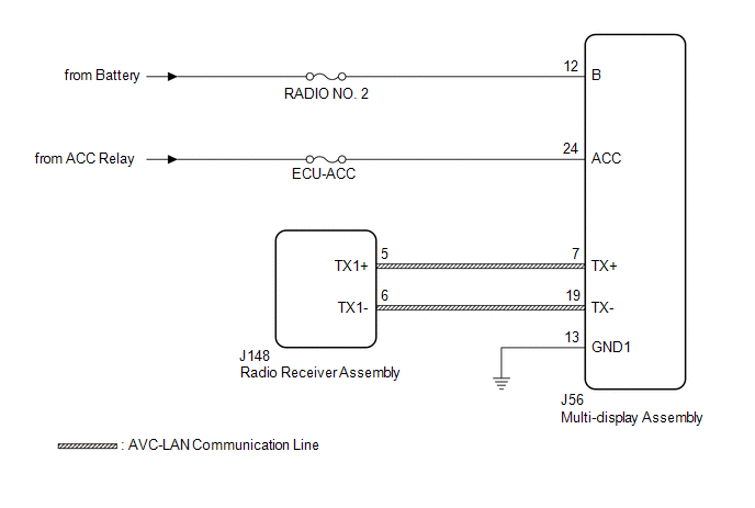
The multi-display assembly and radio receiver assembly are connected by AVC-LAN communication lines.
This DTC is stored when an AVC-LAN communication error occurs between the multi-display assembly and radio receiver assembly.
| DTC No. | Detection Item | DTC Detection Condition | Trouble Area |
|---|---|---|---|
| B15D6 | Display Disconnected | A device that is listed in the AVC-LAN connected device record of the master unit is missing |
|
HINT:
The radio receiver assembly is the master unit.
WIRING DIAGRAM
CAUTION / NOTICE / HINT
NOTICE:
-
Depending on the parts that are replaced during vehicle inspection or maintenance, performing initialization, registration or calibration may be needed. Refer to Precaution for Audio and Visual System.
Click here
.gif)
- Inspect the fuses for circuits related to this system before performing the following procedure.
PROCEDURE
| 1. | CHECK OPTIONAL COMPONENTS (INCLUDING ASSOCIATED WIRING) |
(a) Check for optional components.
(1) Check that optional components (including associated wiring) which generate radio waves are not installed.
| Result | Proceed to |
|---|---|
| Optional components (including associated wiring) are installed. | A |
| Optional components (including associated wiring) are not installed. | B |
HINT:
- Electrical noise from radio waves generated by optional components or the wiring for those components may affect AVC-LAN communication.
- This DTC may be stored when an AVC-LAN communication error occurs due to electrical noise.
| B | .gif) | GO TO STEP 3 |
|
.gif)
| 2. | REMOVE OPTIONAL COMPONENTS (INCLUDING ASSOCIATED WIRING) |
(a) Remove optional components (including associated wiring).
NOTICE:
Do not remove optional components or associated wiring without the permission of the customer.
|
| 3. | CHECK DTC |
(a) Clear the DTCs.
Body Electrical > Navigation System > Clear DTCs(b) Recheck for DTCs and check that no DTCs are output.
Body Electrical > Navigation System > Trouble CodesOK:
No DTCs are output.
| OK | | END |
|
| 4. | CHECK HARNESS AND CONNECTOR (MULTI-DISPLAY ASSEMBLY POWER SOURCE) |
(a) Disconnect the J56 multi-display assembly connector.
(b) Measure the resistance according to the value(s) in the table below.
Standard Resistance:
| Tester Connection | Condition | Specified Condition |
|---|---|---|
| J56-13 (GND1) - Body ground | Always | Below 1 Ω |
(c) Measure the voltage according to the value(s) in the table below.
Standard Voltage:
| Tester Connection | Condition | Specified Condition |
|---|---|---|
| J56-12 (B) - J56-13 (GND1) | Always | 11 to 14 V |
| J56-24 (ACC) - J56-13 (GND1) | Engine switch on (ACC) | 11 to 14 V |
| NG | | REPAIR OR REPLACE HARNESS OR CONNECTOR |
|
| 5. | CHECK HARNESS AND CONNECTOR (RADIO RECEIVER ASSEMBLY - MULTI-DISPLAY ASSEMBLY) |
(a) Disconnect the J148 radio receiver assembly connector.
(b) Disconnect the J56 multi-display assembly connector.
(c) Measure the resistance according to the value(s) in the table below.
Standard Resistance:
| Tester Connection | Condition | Specified Condition |
|---|---|---|
| J148-5 (TX1+) - J56-7 (TX+) | Always | Below 1 Ω |
| J148-6 (TX1-) - J56-19 (TX-) | Always | Below 1 Ω |
| J148-5 (TX1+) or J56-7 (TX+) - Body ground | Always | 10 kΩ or higher |
| J148-6 (TX1-) or J56-19 (TX-) - Body ground | Always | 10 kΩ or higher |
| NG | | REPAIR OR REPLACE HARNESS OR CONNECTOR |
|
| 6. | REPLACE MULTI-DISPLAY ASSEMBLY |
(a) Replace the multi-display assembly with a new or known good one.
Click here
(b) Clear the DTCs.
Body Electrical > Navigation System > Clear DTCs(c) Recheck for DTCs and check that no DTCs are output.
Body Electrical > Navigation System > Trouble CodesOK:
No DTCs are output.
| OK | | END |
| NG | | REPLACE RADIO RECEIVER ASSEMBLY |
 Stereo Component Amplifier Disconnected (B15D3)
DESCRIPTION The radio receiver assembly and stereo component amplifier assembly are connected by AVC-LAN communication lines. This DTC is stored when an AVC-LAN communication error occurs between the ...
 Telematics Transceiver Disconnected (B15DB)
DESCRIPTION If the radio receiver assembly cannot detect the DCM (telematics transceiver) for a certain period of time (90 seconds) after the engine switch is turned on (ACC) and the radio receiver as ...
Other materials:
Lexus RX (RX 350L, RX450h) 2016-2026 Repair Manual > Window / Glass: Front Passenger Side Power Window Switch
ComponentsCOMPONENTS ILLUSTRATION *1 POWER WINDOW REGULATOR SWITCH ASSEMBLY *2 POWER WINDOW REGULATOR SWITCH ASSEMBLY WITH FRONT DOOR UPPER ARMREST BASE PANEL RemovalREMOVAL PROCEDURE 1. REMOVE POWER WINDOW REGULATOR SWITCH ASSEMBLY WITH FRONT DOOR UPPER ARMREST BASE PANEL Click here ...
Lexus RX (RX 350L, RX450h) 2016-2026 Repair Manual > Panoramic View Monitor System: Control Module Communication Bus Off (U0073,U0100,U0126,U0129,U0140,U0163,U0233,U0265-U0268,U1110)
DESCRIPTION These DTCs are stored if there is a malfunction in the CAN communication system connected to the parking assist ECU. HINT: If CAN communication system DTCs are stored, they may also be stored in other systems. DTC No. Detection Item DTC Detection Condition Trouble Area U0073 ...
Lexus RX (RX 350L, RX450h) 2016-{YEAR} Owners Manual
- For your information
- Pictorial index
- For safety and security
- Instrument cluster
- Operation of each component
- Driving
- Lexus Display Audio system
- Interior features
- Maintenance and care
- When trouble arises
- Vehicle specifications
- For owners
Lexus RX (RX 350L, RX450h) 2016-{YEAR} Repair Manual

0.0111