Lexus RX (RX 350L, RX450h) 2016-2026 Repair Manual: Telematics Transceiver Disconnected (B15DB)
DESCRIPTION
If the radio receiver assembly cannot detect the DCM (telematics transceiver) for a certain period of time (90 seconds) after the engine switch is turned on (ACC) and the radio receiver assembly confirms that the information is missing by checking past DCM (telematics transceiver) recognition information (registered information), this DTC will be stored.
The telematics system uses USB communication between devices. If an open, short, short to +B or short to ground occurs in the USB circuit, communication is interrupted and the telematics system will not operate normally.
| DTC No. | Detection Item | DTC Detection Condition | Trouble Area |
|---|---|---|---|
| B15DB | Telematics Transceiver Disconnected | DCM (telematics transceiver) disconnected |
|
HINT:
This DTC may be stored due to environmental reasons such as electrical noise or interference.
WIRING DIAGRAM
.png)
CAUTION / NOTICE / HINT
NOTICE:
-
Depending on the parts that are replaced during vehicle inspection or maintenance, performing initialization, registration or calibration may be needed. Refer to Precaution for Audio and Visual System.
Click here
.gif)
- Inspect the fuses for circuits related to this system before performing the following procedure.
-
Before replacing the DCM (telematics transceiver), refer to Registration.
Click here
PROCEDURE
| 1. | CHECK HARNESS AND CONNECTOR (DCM (TELEMATICS TRANSCEIVER) POWER SOURCE) |
(a) Disconnect the J157 DCM (telematics transceiver) connector.
(b) Measure the resistance according to the value(s) in the table below.
Standard Resistance:
| Tester Connection | Condition | Specified Condition |
|---|---|---|
| J157-20 (E) - Body ground | Always | Below 1 Ω |
(c) Measure the voltage according to the value(s) in the table below.
Standard Voltage:
| Tester Connection | Condition | Specified Condition |
|---|---|---|
| J157-1 (+B) - J157-20 (E) | Always | 11 to 14 V |
| J157-19 (IG2) - J157-20 (E) | Engine switch on (IG) | 11 to 14 V |
| NG | .gif) | REPAIR OR REPLACE HARNESS OR CONNECTOR |
|

| 2. | INSPECT RADIO RECEIVER ASSEMBLY |
(a) Disconnect the J149 radio receiver assembly connector.
| (b) Measure the resistance according to the value(s) in the table below. Standard Resistance:
|
|
.png)
(c) Measure the voltage according to the value(s) in the table below.
Standard Voltage:
| Tester Connection | Condition | Specified Condition |
|---|---|---|
| J149-10 (USBV) - J149-11 (USBG) | Engine switch on (IG) | 4.75 to 5.25 V |
| NG | | REPLACE RADIO RECEIVER ASSEMBLY |
|
| 3. | CHECK HARNESS AND CONNECTOR (RADIO RECEIVER ASSEMBLY - DCM (TELEMATICS TRANSCEIVER)) |
(a) Disconnect the J149 radio receiver assembly connector.
(b) Disconnect the J157 DCM (telematics transceiver) connector.
(c) Measure the resistance according to the value(s) in the table below.
Standard Resistance:
| Tester Connection | Condition | Specified Condition |
|---|---|---|
| J149-10 (USBV) - J157-15 (USBV) | Always | Below 1 Ω |
| J149-11 (USBG) - J157-31 (USBG) | Always | Below 1 Ω |
| J149-10 (USBV) or J157-15 (USBV) - Body ground | Always | 10 kΩ or higher |
| J149-11 (USBG) or J157-31 (USBG) - Body ground | Always | 10 kΩ or higher |
| NG | | REPAIR OR REPLACE HARNESS OR CONNECTOR |
|
| 4. | CHECK HARNESS AND CONNECTOR (RADIO RECEIVER ASSEMBLY - DCM (TELEMATICS TRANSCEIVER)) |
(a) Check the installation condition.
(1) Check the USB communication lines between the radio receiver assembly and DCM (telematics transceiver) for any installation or connection problems.
(b) Disconnect the J167 radio receiver assembly connector.
(c) Disconnect the J168 DCM (telematics transceiver) connector.
| (d) Measure the resistance according to the value(s) in the table below. Standard Resistance:
|
|
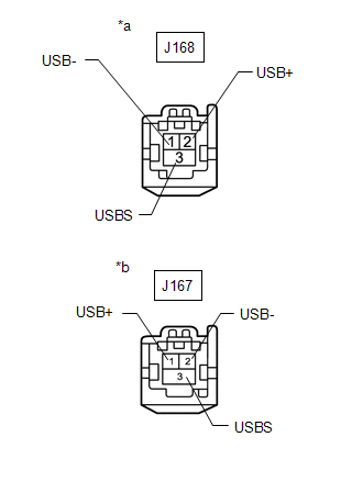
| NG | | REPAIR OR REPLACE HARNESS OR CONNECTOR |
|
| 5. | REPLACE DCM (TELEMATICS TRANSCEIVER) |
(a) Replace the DCM (telematics transceiver) with a new one.
Click here
(b) Clear the DTCs.
Body Electrical > Navigation System > Clear DTCs(c) Turn the engine switch off.
(d) Turn the engine switch on (IG) and wait for 90 seconds.
(e) Recheck for DTCs and check that no DTCs are output.
Body Electrical > Navigation System > Trouble CodesOK:
No DTCs are output.
| OK | | END |
| NG | | REPLACE RADIO RECEIVER ASSEMBLY |
 Display Disconnected (B15D6)
DESCRIPTION The multi-display assembly and radio receiver assembly are connected by AVC-LAN communication lines. This DTC is stored when an AVC-LAN communication error occurs between the multi-display ...
 Air Conditioner ECU Vehicle Information Reading/Writing Processor Malfunction (B15F5)
DESCRIPTION This DTC is stored when items controlled by the air conditioning amplifier assembly cannot be customized via the audio and visual system vehicle customization screen. HINT: The air conditi ...
Other materials:
Lexus RX (RX 350L, RX450h) 2016-2026 Repair Manual > Rear No. 1 Seat Inner Belt Assembly(for 60/40 Split Seat Type Rh Side): Removal
REMOVAL CAUTION / NOTICE / HINT The necessary procedures (adjustment, calibration, initialization or registration) that must be performed after parts are removed and installed, or replaced during rear No. 1 seat inner belt assembly removal/installation are shown below. Necessary Procedure After Part ...
Lexus RX (RX 350L, RX450h) 2016-2026 Repair Manual > Occupant Classification System: Fail-safe Chart
FAIL-SAFE CHART FAIL-SAFE FUNCTION (a) The following chart shows the status of the front passenger SRS items and passenger airbag ON/OFF indicator operation under each condition.
The passenger airbag ON/OFF indicator ("ON" and "OFF") comes on for approximately 4 seconds, then goes off for approxi ...
Lexus RX (RX 350L, RX450h) 2016-{YEAR} Owners Manual
- For your information
- Pictorial index
- For safety and security
- Instrument cluster
- Operation of each component
- Driving
- Lexus Display Audio system
- Interior features
- Maintenance and care
- When trouble arises
- Vehicle specifications
- For owners
Lexus RX (RX 350L, RX450h) 2016-{YEAR} Repair Manual

0.0219