Lexus RX (RX 350L, RX450h) 2016-2026 Repair Manual: Wiper Motor Power Source Circuit
DESCRIPTION
This circuit is the power source circuit for the combination meter assembly. This circuit provides two types of power sources; one is a constant power source, and the other is an IG power source.
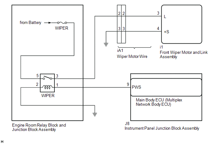
WIRING DIAGRAM
CAUTION / NOTICE / HINT
NOTICE:
Inspect the fuses of circuits related to this system before performing the following procedure.
PROCEDURE
| 1. | READ VALUE USING TECHSTREAM |
(a) Connect the Techstream to the DLC3.
(b) Turn the engine switch on (IG).
(c) Turn the Techstream on.
(d) Enter the following menus: Body Electrical / Wiper / Data List.
(e) Read the Data List according to the display on the Techstream.
Body Electrical > Wiper > Data List| Tester Display | Measurement Item | Range | Normal Condition | Diagnostic Note |
|---|---|---|---|---|
| Status of Power Supply Voltage | Front wiper motor and link assembly input voltage | Normal or Abnormal | Normal: 6.6 to 17.9 V Abnormal: Below 6.5 V or 18.0 V Higher | - |
| Tester Display |
|---|
| Status of Power Supply Voltage |
OK:
The Techstream display is normal.
| OK | .gif) | PROCEED TO NEXT SUSPECTED AREA SHOWN IN PROBLEM SYMPTOMS TABLE |
|
.gif)
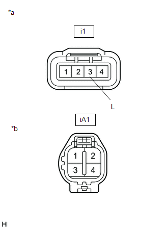
| 2. | CHECK HARNESS AND CONNECTOR (FRONT WIPER MOTOR AND LINK ASSEMBLY - BODY GROUND) |
(a) Disconnect the i1 front wiper motor and link assembly connector.
(b) Measure the resistance according to the value(s) in the table below.
Standard Resistance:
| Tester Connection | Condition | Specified Condition |
|---|---|---|
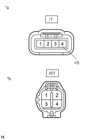
| i1-4 (+S) - Body ground | Always | Below 1 Ω |
| NG | | GO TO STEP 9 |
|
| 3. | CHECK HARNESS AND CONNECTOR (FRONT WIPER MOTOR AND LINK ASSEMBLY - POWER SOURCE) |
(a) Measure the voltage according to the value(s) in the table below.
Standard Voltage:
| Tester Connection | Condition | Specified Condition |
|---|---|---|
| i1-3 (L) - Body ground | Engine switch off | Below 1 V |
| Engine switch on (IG) | 11 to 14 V |
| OK | | REPLACE FRONT WIPER MOTOR AND LINK ASSEMBLY |
|
| 4. | CHECK WIPER MOTOR WIRE |
(a) Remove the wiper motor wire.
Click here .gif)
| (b) Measure the resistance according to the value(s) in the table below. Standard Resistance:
|
|
| NG | | REPLACE WIPER MOTOR WIRE |
|
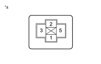
| 5. | INSPECT WIPER RELAY |
(a) Remove the WIPER relay.
(b) Inspect the WIPER relay.
Click here
| NG | | REPLACE WIPER RELAY |
|
| 6. | CHECK HARNESS AND CONNECTOR (FRONT WIPER MOTOR AND LINK ASSEMBLY - POWER SOURCE, BODY GROUND) |
| (a) Measure the voltage according to the value(s) in the table below. Standard Voltage:
|
|
(b) Measure the resistance according to the value(s) in the table below.
Standard Resistance:
| Tester Connection | Condition | Specified Condition |
|---|---|---|
| 2 - Body ground | Always | Below 1 Ω |
| NG | | REPAIR OR REPLACE HARNESS OR CONNECTOR |
|
| 7. | CHECK HARNESS AND CONNECTOR (WIPER RELAY - FRONT WIPER MOTOR AND LINK ASSEMBLY) |
(a) Measure the resistance according to the value(s) in the table below.
Standard Resistance:
| Tester Connection | Condition | Specified Condition |
|---|---|---|
| 3 - i1-3 (L) | Always | Below 1 Ω |
| 3 or i1-3 (L) - Body ground | Always | 10 kΩ or higher |
| NG | | REPAIR OR REPLACE HARNESS OR CONNECTOR |
|
| 8. | CHECK HARNESS AND CONNECTOR (WIPER RELAY - MAIN BODY ECU (MULTIPLEX NETWORK BODY ECU)) |
(a) Disconnect the J8 main body ECU (multiplex network body ECU) connector.
(b) Measure the resistance according to the value(s) in the table below.
Standard Resistance:
| Tester Connection | Condition | Specified Condition |
|---|---|---|
| 1 - J8-9 (PWS) | Always | Below 1 Ω |
| 1 or J8-9 (PWS) - Body ground | Always | 10 kΩ or higher |
| OK | | REPLACE MAIN BODY ECU (MULTIPLEX NETWORK BODY ECU) |
| NG | | REPAIR OR REPLACE HARNESS OR CONNECTOR |
| 9. | CHECK WIPER MOTOR WIRE |
(a) Remove the wiper motor wire.
Click here
| (b) Measure the resistance according to the value(s) in the table below. Standard Resistance:
|
|
| OK | | REPAIR OR REPLACE HARNESS OR CONNECTOR |
| NG | | REPLACE WIPER MOTOR WIRE |
 Rain Sensor Malfunction (B1400)
DESCRIPTION This DTC is stored when the rain sensor detects an internal malfunction. DTC No. Detection Item DTC Detection Condition Trouble Area Memory DTC Output from B1400 Rain Se ...
 Headlight Cleaner Motor and Relay Circuit
DESCRIPTION The headlight cleaner motor and pump assembly is controlled by the headlight ECU sub-assembly RH. When the headlight ECU sub-assembly RH receives the washer switch operation signal 5 times ...
Other materials:
Lexus RX (RX 350L, RX450h) 2016-2026 Repair Manual > Navigation System: Data List / Active Test
DATA LIST / ACTIVE TEST DATA LIST NOTICE: In the table below, the values listed under "Normal Condition" are reference values. Do not depend solely on these reference values when deciding whether a part is faulty or not. HINT: Using the Techstream to read the Data List allows the values or states of ...
Lexus RX (RX 350L, RX450h) 2016-2026 Repair Manual > Audio And Visual System (for 8 Inch Display): Black Screen
PROCEDURE 1. CHECK DISPLAY SETTING (a) Check that the display is not in screen off mode. OK: The display setting is not in screen off mode. NG CHANGE SCREEN TO SCREEN ON MODE
OK 2. CHECK IMAGE QUALITY SETTING (a) Check that the screen color quality can be ...
Lexus RX (RX 350L, RX450h) 2016-{YEAR} Owners Manual
- For your information
- Pictorial index
- For safety and security
- Instrument cluster
- Operation of each component
- Driving
- Lexus Display Audio system
- Interior features
- Maintenance and care
- When trouble arises
- Vehicle specifications
- For owners
Lexus RX (RX 350L, RX450h) 2016-{YEAR} Repair Manual

0.0109