Lexus RX (RX 350L, RX450h) 2016-2026 Repair Manual: Headlight Cleaner Motor and Relay Circuit
DESCRIPTION
The headlight cleaner motor and pump assembly is controlled by the headlight ECU sub-assembly RH. When the headlight ECU sub-assembly RH receives the washer switch operation signal 5 times with the low beam headlights on, it operates the H-LP CLN relay once.
WIRING DIAGRAM
.png)
CAUTION / NOTICE / HINT
NOTICE:
Inspect the fuses of circuits related to this system before performing the following procedure.
PROCEDURE
| 1. | PERFORM ACTIVE TEST USING TECHSTREAM |
(a) Connect the Techstream to the DLC3.
(b) Turn the engine switch on (IG).
(c) Turn the Techstream on.
(d) Enter the following menus: Body Electrical / (desired system) / Active Test.
(e) Perform the Active Test according to the display on the Techstream.
Body Electrical > AFS > Active Test| Tester Display | Measurement Item | Control Range | Diagnostic Note |
|---|---|---|---|
| Headlight Cleaner | Function to operate the headlight cleaner motor | OFF/ON | * |
- *: for Triple Beam Headlight, for Single Beam Headlight with AFS (Adaptive Front-lighting System)
| Tester Display | Measurement Item | Control Range | Diagnostic Note |
|---|---|---|---|
| Headlight Cleaner | Function to operate the headlight cleaner motor | OFF/ON | * |
- *: for Single Beam Headlight without AFS (Adaptive Front-lighting System)
| Tester Display |
|---|
| Headlight Cleaner |
| Tester Display |
|---|
| Headlight Cleaner |
OK:
Headlight cleaner motor and pump assembly is normal.
| NG | .gif) | GO TO STEP 4 |
|
.gif)
| 2. | READ VALUE USING TECHSTREAM |
(a) Connect the Techstream to the DLC3.
(b) Turn the engine switch on (IG).
(c) Turn the Techstream on.
(d) Enter the following menus: Body Electrical / (desired system) / Data List.
(e) Read the Data List according to the display on the Techstream.
Body Electrical > AFS > Data List| Tester Display | Measurement Item | Range | Normal Condition | Diagnostic Note |
|---|---|---|---|---|
| Front Window Washer Switch | Washer switch ON position signal | ON or OFF | ON: Washer switch in ON position OFF: Washer switch not in ON position | * |
- *: for Triple Beam Headlight, for Single Beam Headlight with AFS (Adaptive Front-lighting System)
| Tester Display | Measurement Item | Range | Normal Condition | Diagnostic Note |
|---|---|---|---|---|
| Front Window Washer Switch | Washer switch ON position signal | ON or OFF | ON: Washer switch in ON position OFF: Washer switch not in ON position | * |
- *: for Single Beam Headlight without AFS (Adaptive Front-lighting System)
| Tester Display |
|---|
| Front Window Washer Switch |
| Tester Display |
|---|
| Front Window Washer Switch |
OK:
The Techstream display changes correctly in response to the front washer switch operation.
| OK | | REPLACE HEADLIGHT ECU SUB-ASSEMBLY RH |
|
| 3. | CHECK HARNESS AND CONNECTOR (HEADLIGHT ECU SUB-ASSEMBLY - WINDSHIELD WIPER SWITCH ASSEMBLY) |
(a) Disconnect the A50 headlight ECU sub-assembly RH connector.
(b) Disconnect the J33 windshield wiper switch assembly connector.
(c) Measure the resistance according to the value(s) in the table below.
Standard Resistance:
| Tester Connection | Condition | Specified Condition |
|---|---|---|
| A50-18 (FRWA) - J33-7 (WF) | Always | Below 1 Ω |
| A50-18 (FRWA) or J33-7 (WF) - Body ground | Always | 10 kΩ or higher |
| OK | | REPLACE HEADLIGHT ECU SUB-ASSEMBLY RH |
| NG | | REPAIR OR REPLACE HARNESS OR CONNECTOR |
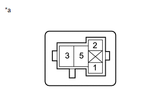
| 4. | INSPECT H-LP CLN RELAY |
(a) Remove the H-LP CLN relay.
(b) Inspect the H-LP CLN relay.
Click here .gif)
| NG | | REPLACE H-LP CLN RELAY |
|
| 5. | CHECK HARNESS AND CONNECTOR (H-LP CLN RELAY - POWER SOURCE) |
| (a) Measure the voltage according to the value(s) in the table below. Standard Voltage:
|
|
| NG | | REPAIR OR REPLACE HARNESS OR CONNECTOR |
|
| 6. | CHECK HARNESS AND CONNECTOR (HEADLIGHT CLEANER MOTOR AND PUMP ASSEMBLY CIRCUIT) |
| (a) Remove the headlight cleaner control relay. |
|

(b) Using a service wire, connect terminal 3 and body ground.
NOTICE:
Do not forcibly insert the service wire into the terminals of the connector when connecting a service wire.
(c) Check the headlight cleaner motor and pump assembly operate.
OK:
Headlight cleaner motor and pump assembly operate.
| NG | | GO TO STEP 9 |
|
| 7. | CHECK HARNESS AND CONNECTOR (H-LP CLN RELAY - BODY GROUND) |
(a) Measure the resistance according to the value(s) in the table below.
Standard Resistance:
| Tester Connection | Condition | Specified Condition |
|---|---|---|
| 5 - Body ground | Always | Below 1 Ω |
| NG | | REPAIR OR REPLACE HARNESS OR CONNECTOR |
|
| 8. | CHECK HARNESS AND CONNECTOR (H-LP CLN RELAY - HEADLIGHT ECU SUB-ASSEMBLY RH) |
(a) Disconnect the A50 headlight ECU sub-assembly RH connector.
(b) Measure the resistance according to the value(s) in the table below.
Standard Resistance:
| Tester Connection | Condition | Specified Condition |
|---|---|---|
| 2 - A50-7 (HLC) | Always | Below 1 Ω |
| 2 or A50-7 (HLC) - Body ground | Always | 10 kΩ or higher |
| OK | | REPLACE HEADLIGHT ECU SUB-ASSEMBLY RH |
| NG | | REPAIR OR REPLACE HARNESS OR CONNECTOR |
| 9. | CHECK HARNESS AND CONNECTOR (HEADLIGHT CLEANER MOTOR AND PUMP ASSEMBLY - POWER SOURCE) |
| (a) Disconnect the A27 headlight cleaner motor and pump assembly connector. |
|
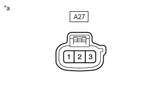
(b) Measure the voltage according to the value(s) in the table below.
Standard Voltage:
| Tester Connection | Condition | Specified Condition |
|---|---|---|
| A27-2 - Body ground | Always | 11 to 14 V |
| NG | | REPAIR OR REPLACE HARNESS OR CONNECTOR |
|
| 10. | INSPECT HEADLIGHT CLEANER MOTOR AND PUMP ASSEMBLY |
(a) Inspect the headlight cleaner motor and pump assembly.
Click here
| NG | | REPLACE HEADLIGHT CLEANER MOTOR AND PUMP ASSEMBLY |
|
| 11. | CHECK HARNESS AND CONNECTOR (HEADLIGHT CLEANER MOTOR AND PUMP ASSEMBLY - H-LP CLN RELAY) |
(a) Disconnect the A27 headlight cleaner motor and pump assembly connector.
(b) Remove the H-LP CLN relay.
(c) Measure the resistance according to the value(s) in the table below.
Standard Resistance:
| Tester Connection | Condition | Specified Condition |
|---|---|---|
| A27-1 - 3 | Always | Below 1 Ω |
| A27-1 or 3 - Body ground | Always | 10 kΩ or higher |
| OK | | USE SIMULATION METHOD TO CHECK |
| NG | | REPAIR OR REPLACE HARNESS OR CONNECTOR |
 Wiper Motor Power Source Circuit
DESCRIPTION This circuit is the power source circuit for the combination meter assembly. This circuit provides two types of power sources; one is a constant power source, and the other is an IG power ...
 Washer Motor Circuit
DESCRIPTION When the washer motor and pump assembly receives signals from the windshield wiper switch assembly it operates to spray washer fluid from the washer nozzle sub-assemblies. WIRING DIAGRAM ...
Other materials:
Lexus RX (RX 350L, RX450h) 2016-2026 Repair Manual > Cooling Fan System: Problem Symptoms Table
PROBLEM SYMPTOMS TABLE HINT:
Use the table below to help determine the cause of problem symptoms. If multiple suspected areas are listed, the potential causes of the symptoms are listed in order of probability in the "Suspected Area" column of the table. Check each symptom by checking the suspect ...
Lexus RX (RX 350L, RX450h) 2016-2026 Repair Manual > Lighting System (w/o Automatic Headlight Beam Level Control System): Terminals Of Ecu
TERMINALS OF ECU CHECK MAIN BODY ECU (MULTIPLEX NETWORK BODY ECU) AND INSTRUMENT PANEL JUNCTION BLOCK ASSEMBLY (a) Disconnect the instrument panel junction block assembly and main body ECU (multiplex network body ECU) connectors. (b) Measure the voltage and resistance according to the value(s) in t ...
Lexus RX (RX 350L, RX450h) 2016-{YEAR} Owners Manual
- For your information
- Pictorial index
- For safety and security
- Instrument cluster
- Operation of each component
- Driving
- Lexus Display Audio system
- Interior features
- Maintenance and care
- When trouble arises
- Vehicle specifications
- For owners
Lexus RX (RX 350L, RX450h) 2016-{YEAR} Repair Manual

0.0096