Lexus RX (RX 350L, RX450h) 2016-2026 Repair Manual: Inspection
INSPECTION
PROCEDURE
1. INSPECT ELECTRICAL KEY TRANSMITTER SUB-ASSEMBLY
(a) Inspect the operation of the electrical key transmitter sub-assembly. (Type A)
(1) Remove the transmitter battery from the electrical key transmitter sub-assembly.
Click here
Click here .gif)
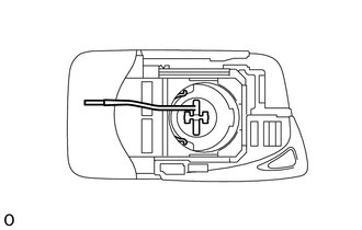
| (2) Install a new or known good transmitter battery. Click here NOTICE: When replacing the transmitter battery, before starting work, remove static electricity that has built up in the body by touching, for example, the vehicle to prevent the electrical key transmitter sub-assembly from being damaged. HINT: If a new or known good transmitter battery is not available, first connect 2 new 1.5 V batteries in series. Then connect leads to the batteries and apply 3 V to the electrical key transmitter sub-assembly, as shown in the illustration. |
|
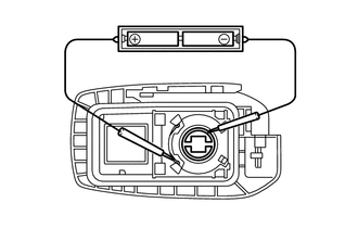
(3) From outside the vehicle, approximately 1 m (3.28 ft.) from the driver door outside door handle, test the electrical key transmitter sub-assembly by pointing its key plate at the vehicle and pressing an electrical key transmitter sub-assembly switch.
OK:
The door lock can be operated via the electrical key transmitter sub-assembly.
The LED comes on more than once.
- The operational area differs depending on the user, the way the electrical key transmitter sub-assembly is held, and the location.
- The weak radio waves of the electrical key transmitter sub-assembly may be affected if the area has strong radio waves or noise. The electrical key transmitter sub-assembly operation area may be shortened or the electrical key transmitter sub-assembly may not function.
(b) Inspect the transmitter battery capacity. (Type A)
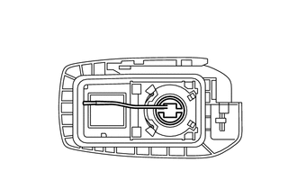
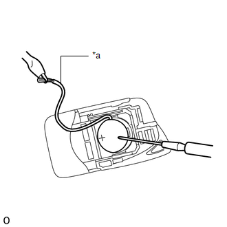
(1) Remove the transmitter battery from the electrical key transmitter sub-assembly that does not operate. Attach a lead wire (0.6 mm (0.0236 in.) in diameter or less including wire sheath) with tape or equivalent to the negative terminal.
Click here
NOTICE:
Do not wrap the lead wire around a terminal, wedge it between the terminals, or solder it. A terminal may be deformed or damaged, and the transmitter battery will not be able to be installed correctly.
| (2) Carefully pull the lead wire out from the position shown in the illustration and install the previously removed transmitter battery. NOTICE: When replacing the transmitter battery, before starting work, remove static electricity that has built up in the body by touching, for example, the vehicle to prevent the electrical key transmitter sub-assembly from being damaged. |
|
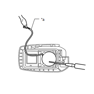
| (3) Check the transmitter battery voltage. HINT:
Standard Voltage:
If the result is not as specified, replace the transmitter battery. |
|
(c) Inspect the operation of the electrical key transmitter sub-assembly. (Type B)
(1) Remove the transmitter battery from the electrical key transmitter sub-assembly.
Click here
| (2) Install a new or known good transmitter battery. Click here NOTICE: When replacing the transmitter battery, before starting work, remove static electricity that has built up in the body by touching, for example, the vehicle to prevent the electrical key transmitter sub-assembly from being damaged. HINT: If a new or known good transmitter battery is not available, first connect 2 new 1.5 V batteries in series. Then connect leads to the batteries and apply 3 V to the electrical key transmitter sub-assembly, as shown in the illustration. |
|
(3) From outside the vehicle, approximately 1 m (3.28 ft.) from the driver door outside door handle, test the electrical key transmitter sub-assembly by pointing its key plate at the vehicle and pressing an electrical key transmitter sub-assembly switch.
OK:
The door lock can be operated via the electrical key transmitter sub-assembly.
The LED comes on more than once.
- The operational area differs depending on the user, the way the electrical key transmitter sub-assembly is held, and the location.
- The weak radio waves of the electrical key transmitter sub-assembly may be affected if the area has strong radio waves or noise. The electrical key transmitter sub-assembly operation area may be shortened or the electrical key transmitter sub-assembly may not function.
(d) Inspect the transmitter battery capacity. (Type B)
(1) Remove the transmitter battery from the electrical key transmitter sub-assembly that does not operate. Attach a lead wire (0.6 mm (0.0236 in.) in diameter or less including wire sheath) with tape or equivalent to the negative terminal.
Click here
NOTICE:
Do not wrap the lead wire around a terminal, wedge it between the terminals, or solder it. A terminal may be deformed or damaged, and the transmitter battery will not be able to be installed correctly.
| (2) Carefully pull the lead wire out from the position shown in the illustration and install the previously removed transmitter battery. NOTICE: When replacing the transmitter battery, before starting work, remove static electricity that has built up in the body by touching, for example, the vehicle to prevent the electrical key transmitter sub-assembly from being damaged. |
|
| (3) Check the transmitter battery voltage. HINT:
Standard Voltage:
If the result is not as specified, replace the transmitter battery. |
|
2. INSPECT ELECTRICAL KEY TRANSMITTER SUB-ASSEMBLY (for Card Type)
(a) Inspect the operation of the electrical key transmitter sub-assembly. (for Card Type)
(1) Remove the transmitter battery from the electrical key transmitter sub-assembly.
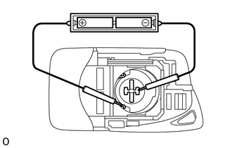
| (2) Install a new or known good transmitter battery. HINT: If a new or known good transmitter battery is not available, connect 2 new 1.5 V batteries in series and connect leads from the batteries to the electrical key transmitter sub-assembly (for Card Type) as shown in the illustration. |
|
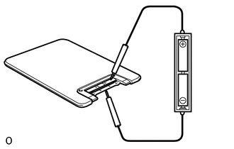
(3) Hold the electrical key transmitter sub-assembly (for Card Type) facing towards the vehicle approximately 1 m (3.28 ft.) away from the driver door outside handle assembly and check that the doors lock when the lock switch on the driver door outside handle assembly is pressed.
OK:
All doors can be locked.
NOTICE:
- Make sure the engine switch is off.
- Make sure to close all doors.
- Do not wedge the tip of the tester lead between the terminals, as a terminal may be deformed or damaged.
(b) Inspect the transmitter battery capacity. (for Card Type)
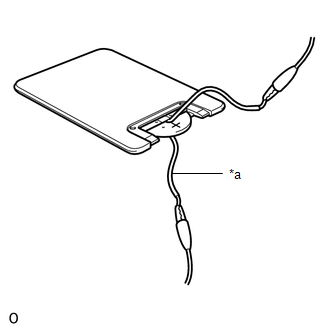
(1) Remove the transmitter battery from the electrical key transmitter sub-assembly (for Card Type) that does not operate. Attach a lead wire to the negative (-) and positive (+) sides of the transmitter battery with tape or equivalent.
NOTICE:
Do not wrap the lead wire around a terminal, wedge it between the terminals, or solder it. A terminal may be deformed or damaged, and the transmitter battery will not be able to be installed correctly.
| (2) Check the transmitter battery voltage. HINT: When measuring the transmitter battery voltage, while operating the lock switch of a door handle, bring the electrical key transmitter sub-assembly (for Card Type) within the entry operation range to perform the measurement. For the entry operation range, refer to Operation Check. Standard Voltage:
If the result is not as specified, replace the transmitter battery. |
|
 Components
COMPONENTS ILLUSTRATION *1 TRANSMITTER BATTERY *2 MECHANICAL KEY *3 TRANSMITTER HOUSING COVER *4 TRANSMITTER HOUSING CASE *5 DOOR CONTROL TRANSMITTER HOUSING SET - - ...
 Front Door Lock
...
Other materials:
Lexus RX (RX 350L, RX450h) 2016-2026 Repair Manual > Combination Switch: Components
COMPONENTS ILLUSTRATION *1 CONSOLE PANEL SUB-ASSEMBLY *2 INSTRUMENT CLUSTER FINISH PANEL ORNAMENT *3 LOWER NO. 1 INSTRUMENT PANEL FINISH PANEL *4 LOWER NO. 2 INSTRUMENT PANEL FINISH PANEL *5 REAR CONSOLE UPPER PANEL *6 SHIFT LEVER KNOB SUB-ASSEMBLY ILLUSTRATION * ...
Lexus RX (RX 350L, RX450h) 2016-2026 Repair Manual > Throttle Body: On-vehicle Inspection
ON-VEHICLE INSPECTION PROCEDURE 1. INSPECT THROTTLE BODY WITH MOTOR ASSEMBLY (a) Before cleaning, or after cleaning the throttle body with motor assembly and installing it to the vehicle, turn the engine switch on (IG) without operating the accelerator pedal sensor assembly. NOTICE: If the accelerat ...
Lexus RX (RX 350L, RX450h) 2016-{YEAR} Owners Manual
- For your information
- Pictorial index
- For safety and security
- Instrument cluster
- Operation of each component
- Driving
- Lexus Display Audio system
- Interior features
- Maintenance and care
- When trouble arises
- Vehicle specifications
- For owners
Lexus RX (RX 350L, RX450h) 2016-{YEAR} Repair Manual

0.0158