Lexus RX (RX 350L, RX450h) 2016-2026 Repair Manual: Driver Side Door Entry Lock and Unlock Functions do not Operate
DESCRIPTION
If the entry lock and unlock functions do not operate for the driver door only, the request code may not be being transmitted from the driver door or the front door outside handle assembly (for driver door) (touch sensor) may be malfunctioning. If the entry functions for other doors operate properly, communication between the electrical key transmitter sub-assembly and door control receiver is normal. In this case, there may be a problem with request code transmission (communication between the certification ECU (smart key ECU assembly) and front door outside handle assembly (for driver door) (electrical key antenna)), or there may be wave interference.
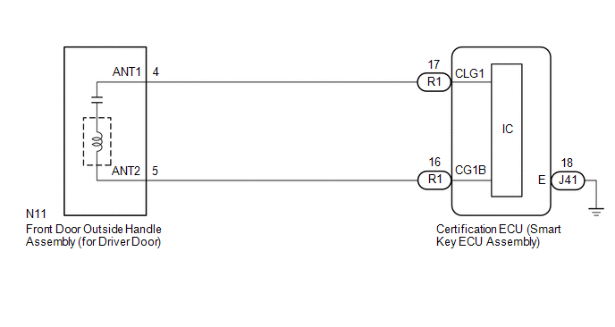
WIRING DIAGRAM
CAUTION / NOTICE / HINT
NOTICE:
-
The smart access system with push-button start (for Entry Function) uses the LIN communication system and CAN communication system. Inspect the communication function by following How to Proceed with Troubleshooting. Troubleshoot the smart access system with push-button start (for Entry Function) after confirming that the communication systems are functioning properly.
Click here
.gif)
- When using the Techstream with the engine switch off, connect the Techstream to the DLC3 and turn a courtesy light switch on and off at intervals of 1.5 seconds or less until communication between the Techstream and the vehicle begins. Then select the vehicle type under manual mode and enter the following menus: Body Electrical / Smart Access. While using the Techstream, periodically turn a courtesy light switch on and off at intervals of 1.5 seconds or less to maintain communication between the Techstream and the vehicle.
- Check that there are no electrical key transmitter sub-assemblies in the vehicle.
-
Before replacing the certification ECU (smart key ECU assembly), refer to Precaution.
Click here
- After repair, confirm that no DTCs are output.
HINT:
- If the driver door entry lock and unlock functions do not operate, the cause of the malfunction may be stored in the certification ECU (smart key ECU assembly).
- If the cause of the malfunction is stored in the certification ECU (smart key ECU assembly), the following table is helpful in checking whether the malfunction was caused by wave interference.
| Tester Display |
|---|
| Operation History |
| Parameter Name | Content |
|---|---|
| Lock / Key RF Signal Interference | When an entry lock operation was performed, the electrical key transmitter sub-assembly could not be confirmed due to wave interference. If the cause of the malfunction has not been stored but the vehicle has been moved and an entry lock operation has been successfully performed, the possibility of wave interference is high. |
| Unlock / Key RF Signal Interference | When an entry unlock operation was performed, the electrical key transmitter sub-assembly could not be confirmed due to wave interference. If the cause of the malfunction has not been stored but the vehicle has been moved and an entry unlock operation has been successfully performed, the possibility of wave interference is high. |
PROCEDURE
| 1. | CHECK POWER DOOR LOCK CONTROL SYSTEM |
(a) When the door control switch on the multiplex network master switch assembly is operated, check that the doors unlock and lock according to the switch operation.
Click here
OK:
Door locks operate normally.
| NG | .gif) | GO TO POWER DOOR LOCK CONTROL SYSTEM |
|
.gif)
| 2. | CHECK FOR DTC |
(a) Check for DTCs.
Body Electrical > Smart Access > Trouble Codes| Result | Proceed to |
|---|---|
| DTCs are not output | A |
| DTCs are output | B |
| B | | GO TO DIAGNOSTIC TROUBLE CODE CHART |
|
| 3. | CHECK WAVE ENVIRONMENT |
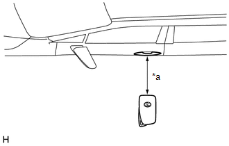
| (a) Bring the electrical key transmitter sub-assembly approximately 0.3 m (0.984 ft.) from the front door outside handle assembly (for driver door) and perform an entry function check. Click here
|
|
| Result | Proceed to |
|---|---|
| Entry function does not operate normally | A |
| Entry function operates normally | B |
| B | | AFFECTED BY WAVE INTERFERENCE |
|
| 4. | READ VALUE USING TECHSTREAM (D-DOOR TOUCH SENSOR) |
(a) Turn the engine switch off.
(b) Open and close the driver door.
(c) With the electrical key transmitter sub-assembly outside of the vehicle, press the lock switch of the electrical key transmitter sub-assembly to lock all of the doors.
(d) Hold the electrical key transmitter sub-assembly at the same height as the door outside handle assembly and approximately 0.3 m (0.984 ft.) from the driver door.
(e) Check that the LED of the electrical key transmitter sub-assembly blinks.
(f) Read the Data List according to the display on the Techstream.
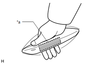
| (g) Touch the unlock sensor on the backside of the front door outside handle assembly (for driver door). HINT: When checking the operation of the unlock sensor again, make sure to perform the procedure from step (a). Body Electrical > Smart Access > Data List
OK: The Techstream display changes correctly in response to the operation of the front door outside handle assembly (for driver door). |
|
| NG | | GO TO STEP 7 |
|
| 5. | READ VALUE USING TECHSTREAM (D-DOOR TRIGGER SWITCH) |
(a) Turn the engine switch off.
(b) Open and close the driver door.
(c) Hold the electrical key transmitter sub-assembly at the same height as the door outside handle assembly and approximately 0.3 m (0.984 ft.) from the driver door.
(d) Read the Data List according to the display on the Techstream.
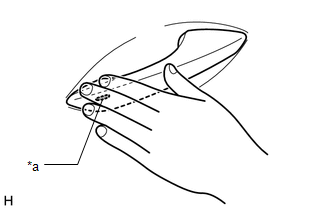
| (e) Touch the lock sensor of the front door outside handle assembly (for driver door). HINT:
HINT: When checking the operation of the entry lock function several times, it can be operated up to 2 times consecutively. To operate the function 3 times or more consecutively, the doors need to be unlocked once. However, this is only for the entry lock function, other door lock operations, such as a wireless door lock operation can be performed consecutively. OK: The Techstream display changes correctly in response to the operation of the front door outside handle assembly (for driver door). |
|
| NG | | GO TO STEP 7 |
|
| 6. | CHECK KEY DIAGNOSTIC MODE |
(a) Check the following antenna in key diagnostic mode.
Body Electrical > Smart Access > Utility| Tester Display |
|---|
| Communication Check(Key Diag Mode) |
(b) Select either channel 1 or channel 2 and perform key diagnostic mode inspection for each channel.
| (1) Check the electrical key antenna (for driver door): When the electrical key transmitter sub-assembly is brought within 0.7 to 1 m (2.30 to 3.28 ft.) of the front door outside handle assembly (for driver door), check that the wireless buzzer sounds. HINT:
|
|
| Result | Proceed to |
|---|---|
| Wireless buzzer does not sound | A |
| Wireless buzzer sounds | B |
| B | | REPLACE CERTIFICATION ECU (SMART KEY ECU ASSEMBLY) |
|
| 7. | CHECK HARNESS AND CONNECTOR (CERTIFICATION ECU (SMART KEY ECU ASSEMBLY) - FRONT DOOR OUTSIDE HANDLE ASSEMBLY (FOR DRIVER DOOR)) |
(a) Disconnect the R1 certification ECU (smart key ECU assembly) connector.
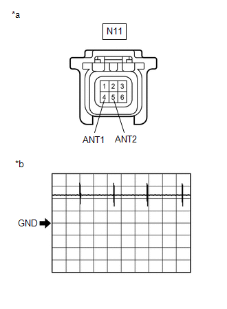
(b) Disconnect the N11 front door outside handle assembly (for driver door) connector.
(c) Measure the resistance according to the value(s) in the table below.
Standard Resistance:
| Tester Connection | Condition | Specified Condition |
|---|---|---|
| R1-17 (CLG1) - N11-4 (ANT1) | Always | Below 1 Ω |
| R1-16 (CG1B) - N11-5 (ANT2) | Always | Below 1 Ω |
| R1-17 (CLG1) or N11-4 (ANT1) - Body ground | Always | 10 kΩ or higher |
| R1-16 (CG1B) or N11-5 (ANT2) - Body ground | Always | 10 kΩ or higher |
(d) Reconnect the R1 certification ECU (smart key ECU assembly) connector.
| NG | | REPAIR OR REPLACE HARNESS OR CONNECTOR |
|
| 8. | CHECK CERTIFICATION ECU (SMART KEY ECU ASSEMBLY) (OUTPUT TO DRIVER DOOR ELECTRICAL KEY ANTENNA) |
| (a) Using an oscilloscope, check the waveform. OK:
*: For details about the entry function detection area, refer to Operation Check. Click here |
|
| NG | | REPLACE CERTIFICATION ECU (SMART KEY ECU ASSEMBLY) |
|
| 9. | CHECK ENTRY LOCK OPERATION |
(a) Connect all connectors and check that the function operates normally.
Click here
| Result | Proceed to |
|---|---|
| Entry function does not operate normally | A |
| Entry function operates normally | B |
| B | | END (CONNECTOR WAS NOT CONNECTED SECURELY) |
|
| 10. | REPLACE FRONT DOOR OUTSIDE HANDLE ASSEMBLY (FOR DRIVER DOOR) |
(a) Replace the front door outside handle assembly (for driver door) with a new one or the front door outside handle assembly (for front passenger door) if it is functioning properly.
Click here
|
| 11. | CHECK ENTRY LOCK OPERATION |
(a) Check that the function operates normally.
Click here
| Result | Proceed to |
|---|---|
| Entry function operates normally | A |
| Entry function does not operate normally | B |
| A | | END (FRONT DOOR OUTSIDE HANDLE ASSEMBLY (FOR DRIVER DOOR) WAS DEFECTIVE) |
| B | | REPLACE CERTIFICATION ECU (SMART KEY ECU ASSEMBLY) |
 Rear Door LH Entry Unlock Function does not Operate
DESCRIPTION If the entry unlock function does not operate for the rear door LH only, but the entry lock function operates, the request code is being transmitted properly from the rear door LH. In this ...
 Entry Interior Alarm does not Sound
DESCRIPTION The smart access system with push-button start (for Entry Function) uses the buzzer in the combination meter assembly (meter ECU) to perform various vehicle interior warnings. When the con ...
Other materials:
Lexus RX (RX 350L, RX450h) 2016-2026 Repair Manual > Audio And Visual System (for 8 Inch Display): Parts Location
PARTS LOCATION ILLUSTRATION *1 TELEPHONE MICROPHONE ASSEMBLY *2 INSTRUMENT PANEL JUNCTION BLOCK ASSEMBLY - ECU-IG2 NO. 3 FUSE (w/ Manual (SOS) Switch) - DCM FUSE (w/ Manual (SOS) Switch) - ECU-DCC NO. 2 FUSE - ECU-ACC FUSE - PANEL FUSE - METER FUSE - METER-IG2 FUSE *3 ENGINE ROOM REL ...
Lexus RX (RX 350L, RX450h) 2016-2026 Repair Manual > Camshaft Position Sensor: Components
COMPONENTS ILLUSTRATION *1 VVT SENSOR (for Intake Side of Bank 1) *2 VVT SENSOR (for Exhaust Side of Bank 1) *3 VVT SENSOR (for Intake Side of Bank 2) *4 VVT SENSOR (for Exhaust Side of Bank 2) N*m (kgf*cm, ft.*lbf): Specified torque Adhesive 1324 ★ Precoated ...
Lexus RX (RX 350L, RX450h) 2016-{YEAR} Owners Manual
- For your information
- Pictorial index
- For safety and security
- Instrument cluster
- Operation of each component
- Driving
- Lexus Display Audio system
- Interior features
- Maintenance and care
- When trouble arises
- Vehicle specifications
- For owners
Lexus RX (RX 350L, RX450h) 2016-{YEAR} Repair Manual

0.0133