Lexus RX (RX 350L, RX450h) 2016-2026 Repair Manual: Rear Door LH Entry Unlock Function does not Operate
DESCRIPTION
If the entry unlock function does not operate for the rear door LH only, but the entry lock function operates, the request code is being transmitted properly from the rear door LH. In this case, there may be a problem related to the unlock sensor (connection between the certification ECU (smart key ECU assembly) and rear door outside handle assembly LH).
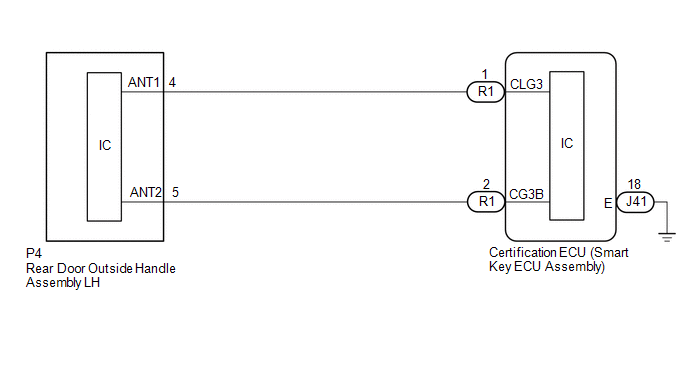
WIRING DIAGRAM
CAUTION / NOTICE / HINT
NOTICE:
-
The smart access system with push-button start (for Entry Function) uses the LIN communication system and CAN communication system. Inspect the communication function by following How to Proceed with Troubleshooting. Troubleshoot the smart access system with push-button start (for Entry Function) after confirming that the communication systems are functioning properly.
Click here
.gif)
- When using the Techstream with the engine switch off, connect the Techstream to the DLC3 and turn a courtesy light switch on and off at intervals of 1.5 seconds or less until communication between the Techstream and the vehicle begins. Then select the vehicle type under manual mode and enter the following menus: Body Electrical / Smart Access. While using the Techstream, periodically turn a courtesy light switch on and off at intervals of 1.5 seconds or less to maintain communication between the Techstream and the vehicle.
- Check that there are no electrical key transmitter sub-assemblies in the vehicle.
-
Before replacing the certification ECU (smart key ECU assembly), refer to Precaution.
Click here
- After repair, confirm that no DTCs are output.
PROCEDURE
| 1. | CHECK POWER DOOR LOCK CONTROL SYSTEM |
(a) When the door control switch on the multiplex network master switch assembly is operated, check that the doors unlock and lock according to the switch operation.
Click here
OK:
Door locks operate normally.
| NG | .gif) | GO TO POWER DOOR LOCK CONTROL SYSTEM |
|
.gif)
| 2. | READ VALUE USING TECHSTREAM (RL-DOOR LOCK POS SW) |
(a) Connect the Techstream to the DLC3.
(b) Turn the engine switch on (IG).
(c) Turn the Techstream on.
(d) Enter the following menus: Body Electrical / Main Body / Data List.
(e) Read the Data List according to the display on the Techstream.
Body Electrical > Main Body > Data List| Tester Display | Measurement Item | Range | Normal Condition | Diagnostic Note |
|---|---|---|---|---|
| RL-Door Lock Pos SW | Rear door LH unlock detection switch signal | ON or OFF | ON: Rear door LH unlocked OFF: Rear door LH locked | - |
| Tester Display |
|---|
| RL-Door Lock Pos SW |
OK:
The Techstream display changes correctly in response to the lock/unlock operation of the rear door LH.
| NG | | GO TO LIGHTING SYSTEM (Proceed to Door Unlock Detection Switch Circuit) |
|
| 3. | READ VALUE USING TECHSTREAM (DR-DOOR TOUCH SENSOR) |
(a) Turn the engine switch off.
(b) Open and close the rear door LH.
(c) With the electrical key transmitter sub-assembly outside of the vehicle, press the lock switch of the electrical key transmitter sub-assembly to lock all of the doors.
(d) Hold the electrical key transmitter sub-assembly at the same height as the door outside handle assembly and approximately 0.3 m (0.984 ft.) from the rear door LH.
(e) Check that the LED of the electrical key transmitter sub-assembly blinks.
(f) Read the Data List according to the display on the Techstream.
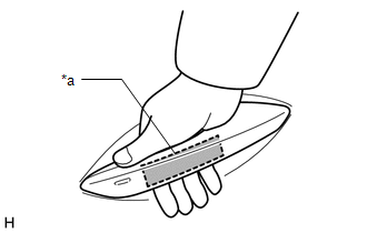
| (g) Touch the unlock sensor on the backside of the front door outside handle assembly (for rear door LH). HINT: When checking the operation of the unlock sensor again, make sure to perform the procedure from step (a). Body Electrical > Smart Access > Data List
OK: The Techstream display changes correctly in response to the operation of the rear door outside handle assembly LH. |
|
| OK | | REPLACE CERTIFICATION ECU (SMART KEY ECU ASSEMBLY) |
|
| 4. | CHECK HARNESS AND CONNECTOR (CERTIFICATION ECU (SMART KEY ECU ASSEMBLY) - REAR DOOR OUTSIDE HANDLE ASSEMBLY LH) |
(a) Disconnect the R1 certification ECU (smart key ECU assembly) connector.
(b) Disconnect the P4 rear door outside handle assembly LH connector.
(c) Measure the resistance according to the value(s) in the table below.
Standard Resistance:
| Tester Connection | Condition | Specified Condition |
|---|---|---|
| R1-1 (CLG3) - P4-4 (ANT1) | Always | Below 1 Ω |
| R1-2 (CG3B) - P4-5 (ANT2) | Always | Below 1 Ω |
| R1-1 (CLG3) or P4-4 (ANT1) - Body ground | Always | 10 kΩ or higher |
| R1-2 (CG3B) or P4-5 (ANT2) - Body ground | Always | 10 kΩ or higher |
(d) Reconnect the P4 rear door outside handle assembly LH connector.
(e) Reconnect the R1 certification ECU (smart key ECU assembly) connector.
| NG | | REPAIR OR REPLACE HARNESS OR CONNECTOR |
|
| 5. | CHECK REAR DOOR OUTSIDE HANDLE ASSEMBLY LH (INPUT TO CERTIFICATION ECU (SMART KEY ECU ASSEMBLY)) |
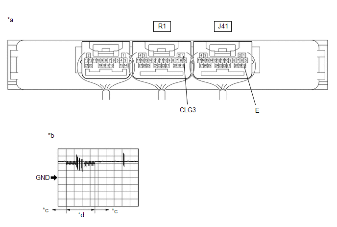
| *a | Component with harness connected (Certification ECU (Smart Key ECU Assembly)) | *b | Waveform 1 |
| *c | Unlock sensor not touched | *d | Unlock sensor touched |
(a) Using an oscilloscope, check the waveform.
OK:
| Tester Connection | Condition | Tool Setting | Specified Condition |
|---|---|---|---|
| R1-1 (CLG3) - J41-18 (E) | Procedure:
| 5 V/DIV., 50 ms/DIV. | Pulse generation (See waveform 1) |
| OK | | REPLACE CERTIFICATION ECU (SMART KEY ECU ASSEMBLY) |
| NG | | REPLACE REAR DOOR OUTSIDE HANDLE ASSEMBLY LH |
 Front Passenger Side Door Entry Unlock Function does not Operate
DESCRIPTION If the entry unlock function does not operate for the front passenger door only, but the entry lock function operates, the request code is being transmitted properly from the front passeng ...
 Driver Side Door Entry Lock and Unlock Functions do not Operate
DESCRIPTION If the entry lock and unlock functions do not operate for the driver door only, the request code may not be being transmitted from the driver door or the front door outside handle assembly ...
Other materials:
Lexus RX (RX 350L, RX450h) 2016-2026 Repair Manual > Power Back Door System (w/ Outside Door Control Switch): Back Door Closer Operation Malfunction (B2250)
DESCRIPTION The multiplex network door ECU receives signals from the latch switch, position switch, pawl switch and back door courtesy switch, which are built into the back door lock assembly. Based on these signals, the latch position of the back door lock assembly is determined. DTC No. Detec ...
Lexus RX (RX 350L, RX450h) 2016-2026 Repair Manual > Rear Seatback Heater (for Captain Seat Type): Removal
REMOVAL CAUTION / NOTICE / HINT The necessary procedures (adjustment, calibration, initialization or registration) that must be performed after parts are removed and installed, or replaced during rear seatback heater removal/installation are shown below. Necessary Procedure After Parts Removed/Insta ...
Lexus RX (RX 350L, RX450h) 2016-{YEAR} Owners Manual
- For your information
- Pictorial index
- For safety and security
- Instrument cluster
- Operation of each component
- Driving
- Lexus Display Audio system
- Interior features
- Maintenance and care
- When trouble arises
- Vehicle specifications
- For owners
Lexus RX (RX 350L, RX450h) 2016-{YEAR} Repair Manual

0.0153