Lexus RX (RX 350L, RX450h) 2016-2026 Repair Manual: Removal
REMOVAL
CAUTION / NOTICE / HINT
The necessary procedures (adjustment, calibration, initialization or registration) that must be performed after parts are removed and installed, or replaced during rear seatback heater removal/installation are shown below.
Necessary Procedure After Parts Removed/Installed/Replaced| Replaced Part or Performed Procedure | Necessary Procedures | Effect/Inoperative Function When Necessary Procedures are not Performed | Link |
|---|---|---|---|
| Disconnect cable from negative battery terminal | Memorize steering angle neutral point | Lane Control System | |
| Pre-collision System | |||
| Intelligent Clearance Sonar System*1 | |||
| Parking Assist Monitor System | | ||
| Panoramic View Monitor System | | ||
| Lighting System (w/ Automatic Headlight Beam Level Control System) | | ||
| Initialize back door lock | Power Door Lock Control System | | |
| Reset back door close position | Power Back Door System (w/ Outside Door Control Switch) | |
*1: When performing learning using the Techstream.
Click here .gif)
CAUTION:
-
Be sure to read Precaution thoroughly before servicing.
Click here
- Wear protective gloves. Sharp areas on the parts may injure your hands.
.png)
HINT:
- Use the same procedure for the RH side and LH side.
- The following procedure is for the LH side.
PROCEDURE
1. REMOVE REAR NO. 1 SEAT ASSEMBLY LH
Click here
2. REMOVE REAR SEAT COVER CAP LH
Click here
3. REMOVE NO. 1 RECLINING ADJUSTER RELEASE HANDLE LH
Click here
4. REMOVE REAR SEAT LOCK CONTROL LEVER SUB-ASSEMBLY LH
Click here
5. REMOVE CUP HOLDER ASSEMBLY
Click here
6. REMOVE REAR SEAT INNER RECLINING COVER LH
Click here
7. REMOVE SEPARATE TYPE REAR SEAT CUSHION COVER WITH PAD
Click here
8. REMOVE REAR SEATBACK COVER LH
Click here
9. REMOVE REAR SEATBACK BOARD CARPET ASSEMBLY LH
Click here
10. REMOVE NO. 1 SEAT ARMREST CAP
Click here
11. REMOVE REAR SEAT ARMREST ASSEMBLY LH
Click here
12. REMOVE REAR SEAT UPPER RECLINING COVER LH
Click here
13. REMOVE RECLINING REMOTE CONTROL LEVER SUB-ASSEMBLY LH
Click here
14. REMOVE SEPARATE TYPE REAR SEATBACK COVER WITH PAD
Click here
15. REMOVE SEPARATE TYPE REAR SEATBACK COVER
Click here
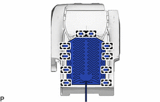
16. REMOVE SEAT HEATER ASSEMBLY
| (a) Remove the 10 tag pins and seat heater assembly from the separate type rear seatback cover. |
|
 Inspection
INSPECTION PROCEDURE 1. INSPECT SEAT HEATER ASSEMBLY (for LH Side) (a) Measure the resistance according to the value(s) in the table below. Standard Resistance: Tester Connection Condition ...
 Installation
INSTALLATION CAUTION / NOTICE / HINT CAUTION: Wear protective gloves. Sharp areas on the seat frame may injure your hands. HINT:
Use the same procedure for the RH side and LH side.
The following ...
Other materials:
Lexus RX (RX 350L, RX450h) 2016-2026 Repair Manual > Audio And Visual System (for 8 Inch Display): Steering Pad Switch Circuit
DESCRIPTION This circuit sends an operation signal from the steering pad switch assembly to the radio receiver assembly. If there is an open in the circuit, the audio system cannot be operated using the steering pad switch assembly. If there is a short in the circuit, the same condition as when a sw ...
Lexus RX (RX 350L, RX450h) 2016-2026 Repair Manual > Outer Rear View Mirror Glass: Removal
REMOVAL CAUTION / NOTICE / HINT HINT:
Use the same procedure for the RH side and LH side.
The following procedure is for the LH side.
PROCEDURE 1. REMOVE OUTER MIRROR (a) Apply protective tape to the areas shown in the illustration. Protective Tape (b) Push the upper part of the mi ...
Lexus RX (RX 350L, RX450h) 2016-{YEAR} Owners Manual
- For your information
- Pictorial index
- For safety and security
- Instrument cluster
- Operation of each component
- Driving
- Lexus Display Audio system
- Interior features
- Maintenance and care
- When trouble arises
- Vehicle specifications
- For owners
Lexus RX (RX 350L, RX450h) 2016-{YEAR} Repair Manual

0.0102