Lexus RX (RX 350L, RX450h) 2016-2026 Repair Manual: Terminals Of Ecm
TERMINALS OF ECM
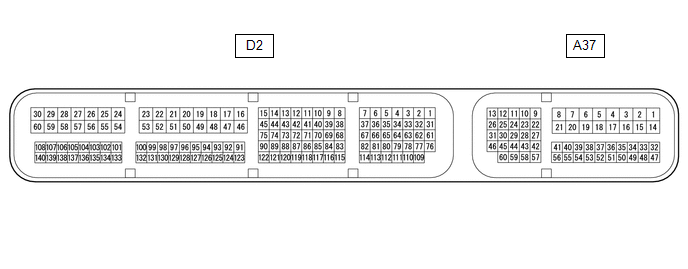
ECM
HINT:
The standard voltage and resistance of each ECM terminal is shown in the table below.
In the table, first follow the information under "Condition". Look under "Terminal No. (Symbol)" for the terminals to be inspected. The standard voltage or resistance between the terminals is shown under "Specified Condition".
Use the illustration above as a reference for the ECM terminals.
| Terminal No. (Symbol) | Wiring Color | Terminal Description | Condition | Specified Condition |
|---|---|---|---|---|
| A37-1 (BATT) - D2-53 (E1) | G - BR | Battery (for measuring battery voltage and for ECM memory) | Always | 11 to 14 V |
| A37-2 (+B) - D2-53 (E1) | R - BR | Power source of ECM | Engine switch on (IG) | 11 to 14 V |
| A37-3 (+B2) - D2-53 (E1) | L - BR | Power source of ECM | Engine switch on (IG) | 11 to 14 V |
| A37-13 (CANH) - D2-53 (E1) | Y - BR | CAN communication line | Engine switch on (IG) | Pulse generation |
| A37-17 (S) - D2-53 (E1) | B - BR | M shift position switch signal | Engine switch on (IG) and shift lever in M | 11 to 14 V |
| Engine switch on (IG) and shift lever not in M | Below 1 V | |||
| A37-26 (CANL) - D2-53 (E1) | P - BR | CAN communication line | Engine switch on (IG) | Pulse generation |
| A37-27 (STP) - D2-53 (E1) | Y - BR | Stop light switch signal | Brake pedal depressed | 7.5 to 14 V |
| Brake pedal released | Below 1 V | |||
| A37-37 (SFTD) - D2-53 (E1) | BE - BR | Down-shift switch signal | Engine switch on (IG) | 11 to 14 V |
| Engine switch on (IG) and shift lever held in "-" (Down shift) | Below 1 V | |||
| Engine switch on (IG) and "-" shift paddle switch pulled | Below 1 V | |||
| A37-38 (SFTU) - D2-53 (E1) | V - BR | Up-shift switch signal | Engine switch on (IG) | 11 to 14 V |
| Engine switch on (IG) and shift lever held in "+" (Up shift) | Below 1 V | |||
| Engine switch on (IG) and "+" shift paddle switch pulled | Below 1 V | |||
| A37-40 (SPCN) - D2-53 (E1) | SB - BR | Pattern select switch (NORMAL) signal | Engine switch on (IG) and pattern select switch being pushed and held at NORMAL position | Below 1.5 V |
| Engine switch on (IG) and pattern select switch not pushed | 11 to 14 V | |||
| A37-43 (STA) - D2-53 (E1) | B - BR | Starter signal | Cranking (shift lever in P or N, engine switch on (START)) | 11 to 14 V |
| Engine switch on (IG) and shift lever in P or N | Below 2 V | |||
| A37-55 (PWMS) - D2-53 (E1) | GR - BR | Pattern select switch (SPORT) signal | Engine switch on (IG) and pattern select switch being turned and held at SPORT position | Below 1.5 V |
| Engine switch on (IG) and pattern select switch not turned | 11 to 14 V | |||
| D2-6 (SL2+) - D2-7 (SL2-) | LG - Y | Shift solenoid valve SL2 signal | 5th, 6th, 7th or 8th gear | Pulse generation |
| D2-10 (SL5+) - D2-11 (SL5-) | W - Y | Shift solenoid valve SL5 signal | 2nd or 8th gear | Pulse generation |
| D2-12 (SL4+) - D2-13 (SL4-) | LG - GR | Shift solenoid valve SL4 signal | 4th or 6th gear | Pulse generation |
| D2-14 (SL1+) - D2-15 (SL1-) | Y - BR | Shift solenoid valve SL1 signal | 1st, 2nd, 3rd, 4th or 5th gear | Pulse generation |
| D2-31 (SL3+) - D2-1 (SL3-) | GR - B | Shift solenoid valve SL3 signal | 3rd or 7th gear | Pulse generation |
| D2-53 (E1) - Body ground | BR - Body ground | Ground | Always | Below 1 Ω |
| D2-62 (S1) - D2-53 (E1) | G - BR | Shift solenoid valve S1 signal |
| 11 to 14 V |
| D2-67 (SLT+) - D2-37 (SLT-) | L - GR | Shift solenoid valve SLT signal | Engine idling | Pulse generation |
| D2-72 (NCO) - D2-53 (E1) | Y - BR | Transmission Revolution Sensor (NC) signal | Vehicle being driven | Pulse generation |
| D2-73 (NCB) - D2-53 (E1) | L - BR | Power source for sensor (specific voltage) | Engine switch on (IG) | 11 to 14 V |
| D2-74 (NTO) - D2-53 (E1) | B - BR | Transmission Revolution Sensor (NT) signal | Engine idling (shift lever in P or N) | Pulse generation |
| D2-75 (NTB) - D2-53 (E1) | Y - BR | Power source for sensor (specific voltage) | Engine switch on (IG) | 11 to 14 V |
| D2-76 (SLU+) - D2-61 (SLU-) | L - B | Shift solenoid valve SLU signal |
| Pulse generation |
| D2-77 (S2) - D2-53 (E1) | BE - BR | Shift solenoid valve S2 signal | 3rd gear | 11 to 14 V |
| D2-78 (NC3B) - D2-53 (E1) | B - BR | Power source for sensor (specific voltage) | Engine switch on (IG) | 11 to 14 V |
| D2-86 (THO1) - D2-133 (ETHW) | W - BR | ATF temperature sensor signal | ATF temperature 115°C (239°F) or higher | Below 1.5 V |
| D2-106 (NSW) - D2-53 (E1) | V - BR | Park/neutral position switch signal | Engine switch on (IG) and shift lever in P or N | Below 1 V |
| Engine switch on (IG) and shift lever not in P or N | 11 to 14 V | |||
| D2-107 (R) - D2-53 (E1) | GR - BR | R shift position switch signal | Engine switch on (IG) and shift lever in R | 11 to 14 V |
| Engine switch on (IG) and shift lever not in R | Below 1 V | |||
| D2-108 (P) - D2-53 (E1) | V - BR | P shift position switch signal | Engine switch on (IG) and shift lever in P | 11 to 14 V |
| Engine switch on (IG) and shift lever not in P | Below 1 V | |||
| D2-110 (NC3O) - D2-53 (E1) | W - BR | Transmission Revolution Sensor (NC3) signal | 1st, 3rd, 4th, 5th, 6th or 7th gear | Pulse generation |
| D2-139 (D) - D2-53 (E1) | B - BR | D shift position switch signal | Engine switch on (IG) and shift lever in D or M | 11 to 14 V |
| Engine switch on (IG) and shift lever not in D or M | Below 1 V | |||
| D2-140 (N) - D2-53 (E1) | BR - BR | N shift position switch signal | Engine switch on (IG) and shift lever in N | 11 to 14 V |
| Engine switch on (IG) and shift lever not in N | Below 1 V |
 Problem Symptoms Table
PROBLEM SYMPTOMS TABLE HINT:
Use the table below to help determine the cause of problem symptoms. If multiple suspected areas are listed, the potential causes of the symptoms are listed in order of ...
 Diagnosis System
DIAGNOSIS SYSTEM DESCRIPTION (a) When troubleshooting On-Board Diagnostic (OBD II) vehicles, an OBD II scan tool (complying with SAE J1978) must be connected to the vehicle. Various data output from t ...
Other materials:
Lexus RX (RX 350L, RX450h) 2016-2026 Repair Manual > Rear Center Seat Inner Belt Assembly(w/ Rear No. 2 Seat): Installation
INSTALLATION PROCEDURE 1. INSTALL REAR CENTER SEAT INNER BELT ASSEMBLY (a) Install the rear center seat inner belt assembly with the bolt. Torque: 42 N·m {428 kgf·cm, 31 ft·lbf} NOTICE: Do not allow the anchor part of the rear center seat inner belt assembly to overlap the protruding parts of th ...
Lexus RX (RX 350L, RX450h) 2016-2026 Repair Manual > Meter / Gauge System: Parts Location
PARTS LOCATION ILLUSTRATION *A w/ Adaptive Variable Suspension System - - *1 FUEL SENDER GAUGE ASSEMBLY *2 VACUUM WARNING SWITCH ASSEMBLY *3 LEVEL WARNING SWITCH ASSEMBLY *4 BRAKE ACTUATOR ASSEMBLY - SKID CONTROL ECU *5 BRAKE MASTER CYLINDER RESERVOIR ASSEMBLY - B ...
Lexus RX (RX 350L, RX450h) 2016-{YEAR} Owners Manual
- For your information
- Pictorial index
- For safety and security
- Instrument cluster
- Operation of each component
- Driving
- Lexus Display Audio system
- Interior features
- Maintenance and care
- When trouble arises
- Vehicle specifications
- For owners
Lexus RX (RX 350L, RX450h) 2016-{YEAR} Repair Manual

0.014