
Lexus RX (RX 350L, RX450h) 2016-2026 Repair Manual: Removal
REMOVAL
CAUTION / NOTICE / HINT
The necessary procedures (adjustment, calibration, initialization or registration) that must be performed after parts are removed and installed, or replaced during front door lock with motor assembly removal/installation are shown below.
Necessary Procedures After Parts Removed/Installed/Replaced| Replaced Part or Performed Procedure | Necessary Procedure | Effect/Inoperative Function when Necessary Procedure not Performed | Link |
|---|---|---|---|
|
*1: When performing learning using the Techstream.
Click here | |||
| Disconnect cable from negative battery terminal | Memorize steering angle neutral point | Lane Control System | |
| Pre-collision System | |||
| Intelligent Clearance Sonar System*1 | |||
| Lighting System (w/ Automatic Headlight Beam Level Control System) | | ||
| Parking Assist Monitor System | | ||
| Panoramic View Monitor System | | ||
| Initialize back door lock | Power Door Lock Control System | | |
| Reset back door close position | Power Back Door System (w/ Outside Door Control Switch) | | |
| Initialize Power Window Control System |
| |
HINT:
- Use the same procedure for the RH side and LH side.
- The following procedure is for the LH side.
PROCEDURE
1. PRECAUTION
NOTICE:
After turning the engine switch off, waiting time may be required before disconnecting the cable from the negative (-) battery terminal. Therefore, make sure to read the disconnecting the cable from the negative (-) battery terminal notices before proceeding with work.
Click here .gif)
2. DISCONNECT CABLE FROM NEGATIVE BATTERY TERMINAL
NOTICE:
When disconnecting the cable, some systems need to be initialized after the cable is reconnected.
Click here
3. REMOVE FRONT DOOR INSIDE HANDLE BEZEL PLUG
Click here
4. REMOVE MULTIPLEX NETWORK MASTER SWITCH ASSEMBLY WITH FRONT DOOR UPPER ARMREST BASE PANEL (for Driver Side)
Click here
5. REMOVE POWER WINDOW REGULATOR SWITCH ASSEMBLY WITH FRONT DOOR UPPER ARMREST BASE PANEL (for Front Passenger Side)
Click here
6. REMOVE DOOR ARMREST COVER
Click here
7. REMOVE COURTESY LIGHT ASSEMBLY
Click here
8. REMOVE FRONT DOOR NO. 1 STIFFENER CUSHION
Click here
9. REMOVE FRONT DOOR TRIM BOARD SUB-ASSEMBLY
Click here
10. REMOVE FRONT DOOR NO. 1 TRIM BRACKET
Click here
11. REMOVE FRONT DOOR SERVICE HOLE COVER
Click here
12. REMOVE FRONT DOOR GLASS SUB-ASSEMBLY
Click here
13. REMOVE FRONT DOOR GLASS RUN
Click here
14. REMOVE FRONT DOOR REAR LOWER FRAME SUB-ASSEMBLY
Click here
15. REMOVE FRONT DOOR OUTSIDE HANDLE ASSEMBLY (for Driver Side)
Click here
16. REMOVE FRONT DOOR LOCK CYLINDER ASSEMBLY (for Driver Side)
Click here
17. REMOVE FRONT DOOR LOCK WITH MOTOR ASSEMBLY
(a) Using a T30 "TORX" socket wrench, remove the 3 screws.
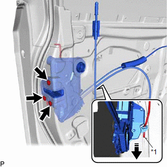
| *1 | Front Door Lock Open Rod |
.png) | Remove in this Direction |
(b) Slide the front door lock with motor assembly downward to disconnect the front door lock open rod and remove the front door lock with motor assembly and cables as a unit.
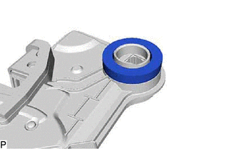
(c) When reusing the front door lock with motor assembly:
| (1) Remove the door lock wiring harness seal from the front door lock with motor assembly. |
|
18. REMOVE FRONT DOOR LOCK COVER SUB-ASSEMBLY
| (a) Using a screwdriver, disengage the 2 claws as shown in the illustration. |
|
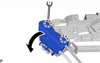
(b) Disengage the 2 claws to remove the front door lock cover sub-assembly as shown in the illustration.
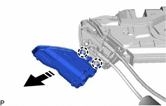
| | Remove in this Direction |
19. REMOVE FRONT DOOR LOCK REMOTE CONTROL CABLE ASSEMBLY
(a) Remove the front door lock remote control cable assembly as shown in the illustration.
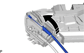
| | Remove in this Direction |
20. REMOVE FRONT DOOR INSIDE LOCKING CABLE ASSEMBLY
(a) Remove the front door inside locking cable assembly as shown in the illustration.
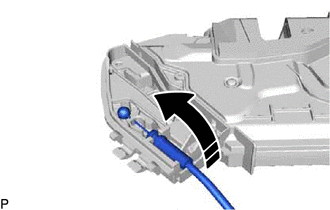
| | Remove in this Direction |
 Inspection
INSPECTION PROCEDURE 1. INSPECT FRONT DOOR LOCK WITH MOTOR ASSEMBLY LH (a) Check the operation of the door lock motor. (1) Apply battery voltage and check the operation of the door lock motor. OK: ...
 Installation
INSTALLATION CAUTION / NOTICE / HINT HINT:
Use the same procedure for the RH side and LH side.
The following procedure is for the LH side.
PROCEDURE 1. PRECAUTION NOTICE: After turning the eng ...
Other materials:
Lexus RX (RX 350L, RX450h) 2016-2026 Repair Manual > Axle And Differential: Front Axle Hub Bolt
ComponentsCOMPONENTS ILLUSTRATION *1 FRONT AXLE HUB BOLT *2 FRONT DISC *3 FRONT DISC BRAKE CALIPER ASSEMBLY - - Tightening torque for "Major areas involving basic vehicle performance such as moving/turning/stopping" : N*m (kgf*cm, ft.*lbf) ● Non-reusable part Repl ...
Lexus RX (RX 350L, RX450h) 2016-2026 Repair Manual > Air Conditioning System: Precaution
PRECAUTION PRECAUTION FOR DISCONNECTING CABLE FROM NEGATIVE BATTERY TERMINAL NOTICE: When disconnecting the cable from the negative (-) battery terminal, initialize the following systems after the cable is reconnected. System Name See Procedure Lane Control System Intelligent Clear ...
Lexus RX (RX 350L, RX450h) 2016-{YEAR} Owners Manual
- For your information
- Pictorial index
- For safety and security
- Instrument cluster
- Operation of each component
- Driving
- Lexus Display Audio system
- Interior features
- Maintenance and care
- When trouble arises
- Vehicle specifications
- For owners
Lexus RX (RX 350L, RX450h) 2016-{YEAR} Repair Manual

0.0107