Lexus RX (RX 350L, RX450h) 2016-2026 Repair Manual: Installation
INSTALLATION
CAUTION / NOTICE / HINT
HINT:
- Use the same procedure for the RH side and LH side.
- The following procedure is for the LH side.
PROCEDURE
1. PRECAUTION
NOTICE:
After turning the engine switch off, waiting time may be required before disconnecting the cable from the negative (-) battery terminal. Therefore, make sure to read the disconnecting the cable from the negative (-) battery terminal notices before proceeding with work.
Click here .gif)
2. INSTALL FRONT DOOR INSIDE LOCKING CABLE ASSEMBLY
(a) Install the front door inside locking cable assembly as shown in the illustration.
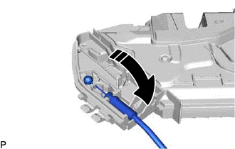
.png) | Install in this Direction |
3. INSTALL FRONT DOOR LOCK REMOTE CONTROL CABLE ASSEMBLY
(a) Install the front door lock remote control cable assembly as shown in the illustration.
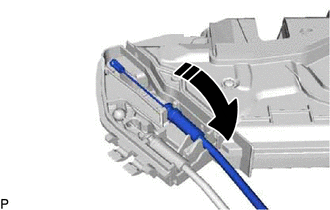
| | Install in this Direction |
4. INSTALL FRONT DOOR LOCK COVER SUB-ASSEMBLY
(a) Engage the 2 claws as shown in the illustration.
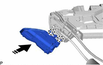
| | Install in this Direction |
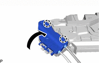
| (b) Engage the 2 claws to install the front door lock cover sub-assembly as shown in the illustration. |
|
5. INSTALL FRONT DOOR LOCK WITH MOTOR ASSEMBLY
NOTICE:
- When reusing a removed front door lock with motor assembly, replace the door lock wiring harness seal with a new one.
- Do not allow grease or dust to adhere to the door lock wiring harness seal installation surface.
- Reusing a door lock wiring harness seal or using a damaged door lock wiring harness seal may cause water ingress. This may result in a malfunction of the front door lock with motor assembly.
(a) Apply MP grease to the sliding parts of the front door lock with motor assembly.
(b) When reusing the front door lock with motor assembly:
(1) Install a new door lock wiring harness seal to the front door lock with motor assembly.
(c) Connect the front door lock open rod to the front door lock with motor assembly.
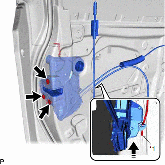
| *1 | Front Door Lock Open Rod |
| | Install in this Direction |
HINT:
Make sure that the front door lock open rod is securely connected to the front door lock with motor assembly.
(d) Using a T30 "TORX" socket wrench, install the front door lock with motor assembly with the 3 screws.
Torque:
5.5 N·m {56 kgf·cm, 49 in·lbf}
6. INSTALL FRONT DOOR LOCK CYLINDER ASSEMBLY (for Driver Side)
Click here
7. INSTALL FRONT DOOR OUTSIDE HANDLE ASSEMBLY (for Driver Side)
Click here
8. INSTALL FRONT DOOR REAR LOWER FRAME SUB-ASSEMBLY
Click here
9. INSTALL FRONT DOOR GLASS RUN
Click here
10. INSTALL FRONT DOOR GLASS SUB-ASSEMBLY
Click here
11. INSTALL FRONT DOOR SERVICE HOLE COVER
Click here
12. INSTALL FRONT DOOR NO. 1 TRIM BRACKET
Click here
13. INSTALL FRONT DOOR TRIM BOARD SUB-ASSEMBLY
Click here
14. INSTALL FRONT DOOR NO. 1 STIFFENER CUSHION
Click here
15. INSTALL COURTESY LIGHT ASSEMBLY
Click here
16. INSTALL DOOR ARMREST COVER
Click here
17. INSTALL MULTIPLEX NETWORK MASTER SWITCH ASSEMBLY WITH FRONT DOOR UPPER ARMREST BASE PANEL (for Driver Side)
Click here
18. INSTALL POWER WINDOW REGULATOR SWITCH ASSEMBLY WITH FRONT DOOR UPPER ARMREST BASE PANEL (for Front Passenger Side)
Click here
19. INSTALL FRONT DOOR INSIDE HANDLE BEZEL PLUG
Click here
20. CONNECT CABLE TO NEGATIVE BATTERY TERMINAL
NOTICE:
When disconnecting the cable, some systems need to be initialized after the cable is reconnected.
Click here
21. INITIALIZE POWER WINDOW CONTROL SYSTEM
Click here
22. INSPECT POWER WINDOW OPERATION
Click here
 Removal
REMOVAL CAUTION / NOTICE / HINT The necessary procedures (adjustment, calibration, initialization or registration) that must be performed after parts are removed and installed, or replaced during fron ...

Other materials:
Lexus RX (RX 350L, RX450h) 2016-2026 Repair Manual > Audio And Visual System (for 8 Inch Display): XM Tuner Antenna Disconnected (B15FE,B15FF)
DESCRIPTION These DTCs are stored when a malfunction occurs in the telephone antenna assembly which is connected to the radio receiver assembly. DTC No. Detection Item DTC Detection Condition Trouble Area B15FE XM Tuner Antenna Disconnected The telephone antenna assembly is not conn ...
Lexus RX (RX 350L, RX450h) 2016-2026 Repair Manual > Luggage Speaker(w/ Rear No. 2 Seat): Removal
REMOVAL PROCEDURE 1. REMOVE TONNEAU COVER ASSEMBLY Click here 2. REMOVE DECK BOARD ASSEMBLY Click here 3. REMOVE REAR NO. 4 FLOOR BOARD Click here 4. REMOVE DECK SIDE TRIM BOX LH Click here 5. REMOVE NO. 1 DECK BOARD Click here 6. DISCONNECT REAR NO. 2 SEAT ASSEMBLY Click here 7. R ...
Lexus RX (RX 350L, RX450h) 2016-{YEAR} Owners Manual
- For your information
- Pictorial index
- For safety and security
- Instrument cluster
- Operation of each component
- Driving
- Lexus Display Audio system
- Interior features
- Maintenance and care
- When trouble arises
- Vehicle specifications
- For owners
Lexus RX (RX 350L, RX450h) 2016-{YEAR} Repair Manual

0.0087