Lexus RX (RX 350L, RX450h) 2016-2026 Repair Manual: Terminals Of Ecu
TERMINALS OF ECU
CHECK INSTRUMENT PANEL JUNCTION BLOCK ASSEMBLY AND MAIN BODY ECU (MULTIPLEX NETWORK BODY ECU)
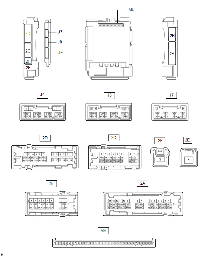
(a) Remove the main body ECU (multiplex network body ECU) from the instrument panel junction block assembly.
(b) Reconnect the instrument panel junction block assembly connector.
(c) Measure the voltage and resistance according to the value(s) in the table below.
| Tester Connection | Wiring Color | Terminal Description | Condition | Specified Condition |
|---|---|---|---|---|
| MB-11 (GND1) - Body ground | - | Ground | Always | Below 1 Ω |
| MB-30 (ACC) - Body ground | - | ACC power supply | Engine switch on (ACC) | 11 to 14 V |
| MB-30 (ACC) - Body ground | - | ACC power supply | Engine switch off | Below 1 V |
| MB-31 (BECU) - Body ground | - | Battery power supply | Always | 11 to 14 V |
| MB-32 (IG) - Body ground | - | IG power supply | Engine switch on (IG) | 11 to 14 V |
| MB-32 (IG) - Body ground | - | IG power supply | Engine switch off | Below 1 V |
(d) Install the main body ECU (multiplex network body ECU) to the instrument panel junction block assembly.
(e) Measure the voltage and check for pulses according to the value(s) in the table below.
| Tester Connection | Wiring Color | Terminal Description | Condition | Specified Condition |
|---|---|---|---|---|
| J9-2 (LSWR) - Body ground | L - Body ground | Rear door RH unlock detection switch input | Rear door RH unlocked | Below 1 V |
| J9-2 (LSWR) - Body ground | L - Body ground | Rear door RH unlock detection switch input | Rear door RH locked | Pulse generation |
| J8-2 (UL3) - Body ground | V - Body ground | Driver door key-linked unlock input | Driver door key cylinder turned to neutral position → on (unlock) | Pulse generation → Below 1 V |
| J8-6 (FLCY) - Body ground | P - Body ground | Front door courtesy light switch (for LH) input | Front door LH open | Below 1 V |
| J8-6 (FLCY) - Body ground | P - Body ground | Front door courtesy light switch (for LH) input | Front door LH closed | Pulse generation |
| J8-27 (FRCY) - Body ground | R - Body ground | Front door courtesy light switch (for RH) input | Front door RH open | Below 1 V |
| J8-27 (FRCY) - Body ground | R - Body ground | Front door courtesy light switch (for RH) input | Front door RH closed | Pulse generation |
| J8-29 (L2) - Body ground | P - Body ground | Driver door key-linked lock input | Driver door key cylinder turned to neutral position → on (lock) | Pulse generation → Below 1 V |
| 2D-8 (ACT-) - Body ground | W - Body ground | Door lock motor unlock drive output | Door control switch or driver door key cylinder off → on (unlock) | Below 1 V → 11 to 14 V → Below 1 V |
| 2D-6 (ACT+) - Body ground | P - Body ground | Door lock motor lock drive output | Door control switch or driver door key cylinder off → on (lock) | Below 1 V → 11 to 14 V → Below 1 V |
| 2D-24 (LCTY) - Body ground | W - Body ground | Rear door courtesy light switch (for LH) input | Rear door LH open | Below 1 V |
| 2D-24 (LCTY) - Body ground | W - Body ground | Rear door courtesy light switch (for LH) input | Rear door LH closed | Pulse generation |
| 2B-14 (LSWL) - Body ground | V - Body ground | Rear door LH unlock detection switch input | Rear door LH unlocked | Below 1 V |
| 2B-14 (LSWL) - Body ground | V - Body ground | Rear door LH unlock detection switch input | Rear door LH locked | Pulse generation |
| 2C-29 (BZR) - Body ground | P - Body ground | Wireless door lock buzzer output | Engine switch off, all doors closed, electrical key transmitter sub-assembly no inside vehicle and lock or unlock switch of electrical key transmitter sub-assembly not pressed → pressed (wireless door lock buzzer answer-back) | Below 1 V → Pulse generation |
| 2B-1 (ACT-) - Body ground | B - Body ground | Door lock motor unlock drive output | Door control switch or driver door key cylinder off → on (unlock) | Below 1 V → 11 to 14 V → Below 1 V |
| 2D-9 (ACT-) - Body ground | B - Body ground | Door lock motor unlock drive output | Door control switch or driver door key cylinder off → on (unlock) | Below 1 V → 11 to 14 V → Below 1 V |
| 2B-4 (ACTD) - Body ground | B - Body ground | Door lock motor unlock drive output | Door control switch or driver door key cylinder off → on (unlock) | Below 1 V → 11 to 14 V → Below 1 V |
| 2D-18 (ACT+) - Body ground | B - Body ground | Door lock motor lock drive output | Door control switch or driver door key cylinder off → on (lock) | Below 1 V → 11 to 14 V → Below 1 V |
| 2B-2 (ACT+) - Body ground | R - Body ground | Door lock motor lock drive output | Door control switch or driver door key cylinder off → on (lock) | Below 1 V → 11 to 14 V → Below 1 V |
| 2A-31 (RCTY) - Body ground | R - Body ground | Rear door courtesy light switch (for RH) input | Rear door RH open | Below 1 V |
| 2A-31 (RCTY) - Body ground | R - Body ground | Rear door courtesy light switch (for RH) input | Rear door RH closed | Pulse generation |
| 2B-12 (LSFR) - Body ground | P - Body ground | Front door RH unlock detection switch input | Front door RH unlocked | Below 1 V |
| 2B-12 (LSFR) - Body ground | P - Body ground | Front door RH unlock detection switch input | Front door RH locked | Pulse generation |
| 2B-13 (LSFL) - Body ground | B - Body ground | Front door LH unlock detection switch input | Front door LH unlocked | Below 1 V |
| 2B-13 (LSFL) - Body ground | B - Body ground | Front door LH unlock detection switch input | Front door LH locked | Pulse generation |
CHECK CERTIFICATION ECU (SMART KEY ECU ASSEMBLY)
.png)
(a) Disconnect the J41 certification ECU (smart key ECU assembly) connector.
(b) Measure the voltage and resistance according to the value(s) in the table below.
| Tester Connection | Wiring Color | Terminal Description | Condition | Specified Condition |
|---|---|---|---|---|
| J41-4 (+B) - Body ground | V - Body ground | Battery power supply | Always | 11 to 14 V |
| J41-18 (E) - Body ground | W-B - Body ground | Ground | Always | Below 1 Ω |
(c) Reconnect the J41 certification ECU (smart key ECU assembly) connector.
(d) Measure the voltage and check for pulses according to the value(s) in the table below.
| Tester Connection | Wiring Color | Terminal Description | Condition | Specified Condition |
|---|---|---|---|---|
| R1-18 (RCO) - J41-18 (E) | LG - W-B | Output to electrical key and tire pressure monitoring system receiver assembly (Power supply for electrical key and tire pressure monitoring system receiver assembly. Certification ECU (smart key ECU assembly) outputs 5 V when receiver starts operating.) | Proceed:
| Below 1 V → 4.5 to 5.5 V |
| R1-20 (CSEL) - J41-18 (E) | SB - W-B | Communication channel switching circuit | Proceed:
| No pulse generation → Pulse generation |
| R1-19 (RDAM) - J41-18 (E) | W - W-B | Electrical key and tire pressure monitoring system receiver assembly communication circuit | Proceed:
| 11 to 14 pulse generation at regular intervals → Pulse generation |
 Problem Symptoms Table
PROBLEM SYMPTOMS TABLE HINT:
Use the table below to help determine the cause of problem symptoms. If multiple suspected areas are listed, the potential causes of the symptoms are listed in order of ...
 Diagnosis System
DIAGNOSIS SYSTEM DESCRIPTION The main body ECU (multiplex network body ECU) stores DTCs when malfunctions occur. The diagnostic system allows for reading of the DTCs from the DLC3. Use the Techstream ...
Other materials:
Lexus RX (RX 350L, RX450h) 2016-2026 Repair Manual > Blind Spot Monitor System: Freeze Frame Data
FREEZE FRAME DATA FREEZE FRAME DATA (a) Whenever DTCs are detected, the blind spot monitor sensor stores the current vehicle (sensor) state as freeze frame data. CHECK FREEZE FRAME DATA (a) Connect the Techstream to the DLC3. (b) Turn the engine switch on (IG). (c) Turn the blind spot monitor system ...
Lexus RX (RX 350L, RX450h) 2016-2026 Repair Manual > Rear Combination Light Assembly (w/ Rear No. 2 Seat): Disassembly
DISASSEMBLY CAUTION / NOTICE / HINT HINT:
Use the same procedure for the RH side and LH side.
The following procedure is for the LH side.
PROCEDURE 1. REMOVE REAR COMBINATION LIGHT CAP (for LED Type Turn Signal Light) (a) for TMMC Made: (1) Remove the rear combination light cap. HINT: Use ...
Lexus RX (RX 350L, RX450h) 2016-{YEAR} Owners Manual
- For your information
- Pictorial index
- For safety and security
- Instrument cluster
- Operation of each component
- Driving
- Lexus Display Audio system
- Interior features
- Maintenance and care
- When trouble arises
- Vehicle specifications
- For owners
Lexus RX (RX 350L, RX450h) 2016-{YEAR} Repair Manual

0.0213