Lexus RX (RX 350L, RX450h) 2016-2026 Repair Manual: Wireless Door Lock Tuner Circuit Malfunction (B1242)
DESCRIPTION
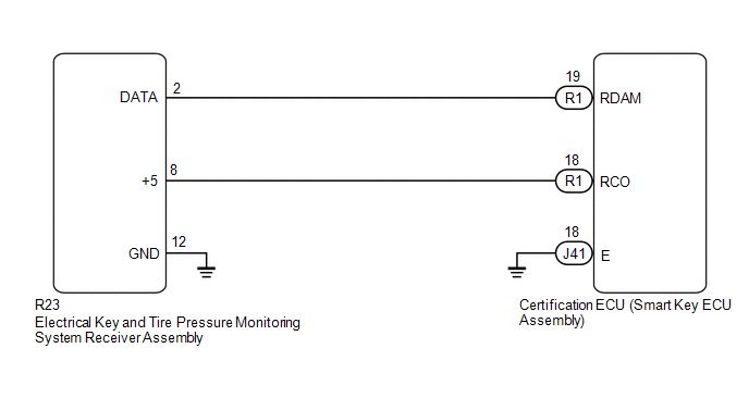
The electrical key and tire pressure monitoring system receiver assembly is used to receive radio waves related to the entry functions of the electrical key transmitter sub-assembly. The certification ECU (smart key ECU assembly) decodes the requested electrical key transmitter sub-assembly operation by identifying a key code based on the radio waves received via the electrical key and tire pressure monitoring system receiver assembly. The electrical key and tire pressure monitoring system receiver assembly receives a signal from the electrical key transmitter sub-assembly and sends signals to the main body ECU (multiplex network body ECU) through the certification ECU (smart key ECU assembly). (ex. If a door lock operation is requested, the certification ECU (smart key ECU assembly) sends a door lock command to the main body ECU (multiplex network body ECU)).
| DTC No. | Detection Item | DTC Detection Condition | Trouble Area |
|---|---|---|---|
| B1242 | Wireless Door Lock Tuner Circuit Malfunction |
|
|
WIRING DIAGRAM
CAUTION / NOTICE / HINT
NOTICE:
- When replacing or inspecting the electrical key and tire pressure monitoring system receiver assembly and wire harness, do not change the position or length of the wire harness. If the wire harness is too close to the electrical key and tire pressure monitoring system receiver assembly, the performance of the entry function and wireless function may be affected.
- This DTC is not stored within 10 seconds of the engine switch being turned from on (IG) to off.
-
The wireless door lock control system uses the CAN communication system. Inspect the communication function by following How to Proceed with Troubleshooting. Troubleshoot the wireless door lock control system after confirming that the communication system is functioning properly.
Click here
.gif)
-
Before replacing the electrical key and tire pressure monitoring system receiver assembly or certification ECU (smart key ECU assembly), refer to Registration.
Click here
-
When replacing the electrical key and tire pressure monitoring system receiver assembly, read the transmitter IDs (tire pressure warning system) stored in the old ECU using the Techstream and write them down before removal.
Click here
-
It is necessary to perform initialization (Click here ) after registration (Click here ) of the transmitter IDs into the electrical key and tire pressure monitoring system receiver assembly if the electrical key and tire pressure monitoring system receiver assembly has been replaced.
PROCEDURE
| 1. | CHECK CERTIFICATION ECU (SMART KEY ECU ASSEMBLY) |
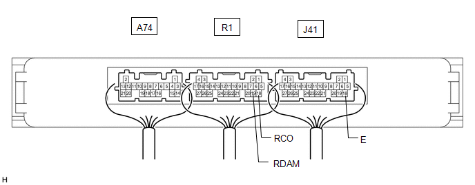
(a) Disconnect the R23 electrical key and tire pressure monitoring system receiver assembly connector.
| *a | Component with harness connected (Certification ECU (Smart Key ECU Assembly)) | - | - |
(b) Measure the voltage and resistance and check for pulses according to the value(s) in the table below.
Standard Voltage:
| Tester Connection | Condition | Specified Condition |
|---|---|---|
| R1-19 (RDAM) - J41-18 (E) | always | 11 to 14 V |
| R1-18 (RCO) - J41-18 (E) | always | Below 1 V → 4.5 to 5.5 V pulse generation at regular intervals |
Standard Resistance:
| Tester Connection | Condition | Specified Condition |
|---|---|---|
| J41-18 (E) - Body ground | Always | Below 1 Ω |
| OK | .gif) | REPLACE ELECTRICAL KEY AND TIRE PRESSURE MONITORING SYSTEM RECEIVER ASSEMBLY |
|
.gif)
| 2. | CHECK HARNESS AND CONNECTOR (ELECTRICAL KEY AND TIRE PRESSURE MONITORING SYSTEM RECEIVER ASSEMBLY - CERTIFICATION ECU (SMART KEY ECU ASSEMBLY)) |
(a) Disconnect the R1 and J41 certification ECU (smart key ECU assembly) connectors.
(b) Measure the resistance according to the value(s) in the table below.
Standard Resistance:
| Tester Connection | Condition | Specified Condition |
|---|---|---|
| R1-19 (RDAM) - R23-2 (DATA) | Always | Below 1 Ω |
| R1-18 (RCO) - R23-8 (+5) | Always | Below 1 Ω |
| R23-12 (GND) - Body ground | Always | Below 1 Ω |
| R23-2 (DATA) or R1-19 (RDAM) - Body ground | Always | 10 kΩ or higher |
| R23-8 (+5) or R1-18 (RCO) - Body ground | Always | 10 kΩ or higher |
| OK | | REPLACE CERTIFICATION ECU (SMART KEY ECU ASSEMBLY) |
| NG | | REPAIR OR REPLACE HARNESS OR CONNECTOR |
 Diagnostic Trouble Code Chart
DIAGNOSTIC TROUBLE CODE CHART Wireless Door Lock Control System DTC No. Detection Item Link B1242 Wireless Door Lock Tuner Circuit Malfunction ...
 No Answer-Back
DESCRIPTION In some cases, wireless door lock control functions are normal but the hazard warning light and/or wireless door lock buzzer answer-back function does not operate. In such cases, hazard wa ...
Other materials:
Lexus RX (RX 350L, RX450h) 2016-2026 Repair Manual > Theft Deterrent / Keyless Entry: Engine Hood Courtesy Switch
ComponentsCOMPONENTS ILLUSTRATION *1 COOL AIR INTAKE DUCT SEAL *2 ENGINE HOOD COURTESY SWITCH (HOOD LOCK ASSEMBLY) *3 HOOD LOCK RELEASE LEVER PROTECTOR - - N*m (kgf*cm, ft.*lbf): Specified torque MP grease InspectionINSPECTION PROCEDURE 1. INSPECT ENGINE HOOD COURT ...
Lexus RX (RX 350L, RX450h) 2016-2026 Repair Manual > Automatic Transaxle System: Check Mode Procedure
CHECK MODE PROCEDURE DESCRIPTION (a) Check mode has a higher sensitivity to malfunctions and can detect malfunctions that normal mode cannot detect. Check mode can also detect all of the malfunctions that normal mode can detect. In check mode, DTCs are detected with 1 trip detection logic. CHECK MOD ...
Lexus RX (RX 350L, RX450h) 2016-{YEAR} Owners Manual
- For your information
- Pictorial index
- For safety and security
- Instrument cluster
- Operation of each component
- Driving
- Lexus Display Audio system
- Interior features
- Maintenance and care
- When trouble arises
- Vehicle specifications
- For owners
Lexus RX (RX 350L, RX450h) 2016-{YEAR} Repair Manual

0.0098