Lexus RX (RX 350L, RX450h) 2016-2026 Repair Manual: Terminals Of Ecu
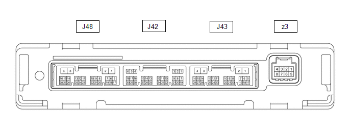
TERMINALS OF ECU
AIR CONDITIONING AMPLIFIER ASSEMBLY (w/o Rear Air Conditioning System)
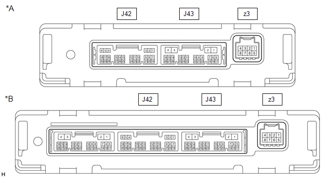
| *A | w/o Seat Heater | *B | w/ Seat Heater |
HINT:
Check from the rear of the connector while it is connected to the air conditioning amplifier assembly.
| Terminal No. (Symbol) | Wiring Color | Terminal Description | Condition | Specified Condition |
|---|---|---|---|---|
| J42-1 (SG-1) - Body ground | L - Body ground | Ground for cooler (room temp. sensor) thermistor | Always | Below 1 V |
| J42-2 (SG-2) - Body ground | B - Body ground | Ground for cooler (ambient temp. sensor) thermistor, A/C lock sensor, smog ventilation sensor*2 | Always | Below 1 V |
| J42-3 (SG-4) - Body ground | BE - Body ground | Ground for air conditioner pressure sensor | Always | Below 1 V |
| J42-6 (S5-3) - J42-2 (SG-2) | W - B | Power supply for air conditioner pressure sensor | Engine switch on (IG) | 4.75 to 5.25 V |
| Engine switch off | Below 1 V | |||
| J42-9 (MGC) - J43-4 (GND) | R - W-B | Magnetic clutch operation signal |
| 11 to 14 V |
| Below 1 V | |||
| J42-10 (PTC2) - J43-4 (GND)*1 | G - W-B | Quick heater assembly operation signal |
| Below 1 V |
| 11 to 14 V | |||
| J42-11 (PTC3) - J43-4 (GND)*1 | Y - W-B | Quick heater assembly operation signal |
| Below 1 V |
| 11 to 14 V | |||
| J42-13 (TAM) - J42-2 (SG-2) | G - B | Cooler (ambient temp. sensor) thermistor signal |
| 1.35 to 1.75 V |
| 0.9 to 1.2 V | |||
| J42-14 (TR) - J42-1 (SG-1) | P - L | Cooler (room temp. sensor) thermistor signal |
| 1.8 to 2.2 V |
| 1.2 to 1.6 V | |||
| J42-20 (ECOS) - J43-4 (GND) | V - W-B | Combination switch assembly (ECO mode switch) signal |
| 11 to 14 V |
| Below 1 V | |||
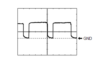
| J42-21 (LOCK) - J42-2 (SG-2) | B - B | A/C lock sensor signal |
| Pulse generation (See waveform 1) |
| J42-24 (PRE) - J42-3 (SG-4) | L - BE | Air conditioner pressure sensor signal |
| 4.61 V or higher |
| Below 0.74 V | |||
| 0.74 to 4.61 V | |||
| J42-25 (DGS) - J42-2 (SG-2)*2 | LG - B | Smog ventilation sensor signal (HC, CO) | 28 seconds after engine switch turned on (IG) and sensor exposed to exhaust gas (HC, CO) | 1.0 to 4.5 V |
| J42-27 (DGS1) - J42-2 (SG-2)*2 | GR - B | Smog ventilation sensor signal (NOx) | 120 seconds after engine switch turned on (IG) and sensor exposed to exhaust gas (NOx) | 1.0 to 4.5 V |
| J43-1 (B) - J43-4 (GND) | R - W-B | Power source (Back-up) | Always | 11 to 14 V |
| J43-2 (IG+) - J43-4 (GND) | GR - W-B | Power source (IG) | Engine switch on (IG) | 11 to 14 V |
| Engine switch off | Below 1 V | |||
| J43-3 (SOL+) - J43-4 (GND) | SB - W-B | Compressor solenoid operation signal |
| Pulse generation (See waveform 2) |
| J43-4 (GND) - Body ground | W-B - Body ground | Ground for main power supply | Always | Below 1 V |
| J43-6 (BLW) - J43-4 (GND) | L - W-B | Blower motor speed control signal |
| Pulse generation (See waveform 3) |
| J43-11 (CANH) - J43-12 (CANL) | LG - W | CAN communication system | CAN communication is performed | Pulse generation |
| J43-18 (PTC1) - J43-4 (GND)*1 | LG - W-B | Quick heater assembly operation signal |
| Below 1 V |
| 11 to 14 V | |||
| z3-2 (BUS G) - Body ground | - | Ground for BUS IC | Always | Below 1 V |
| z3-3 (BUS) - z3-2 (BUS G) | - | BUS IC control signal | Engine switch on (IG) | Pulse generation |
| z3-4 (B BUS) - z3-2 (BUS G) | - | Power supply for BUS IC | Always | 11 to 14 V |
| z3-5 (SGA) - Body ground | - | Ground for No. 1 cooler thermistor | Always | Below 1 V |
| z3-6 (TEA) - z3-5 (SGA) | - | No. 1 cooler thermistor signal |
| 2.0 to 2.4 V |
| 1.4 to 1.8 V |
- *1: w/ PTC Heater
- *2: w/ Smog Ventilation Sensor
(a) Waveform 1:
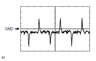
| Item | Content |
|---|---|
| Terminal No. | J42-21 (LOCK) - J42-2 (SG-2) |
| Tool Setting | 200 mV/DIV., 10 ms./DIV. |
| Vehicle Condition |
|
(b) Waveform 2:
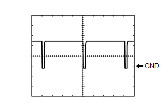
| Item | Content |
|---|---|
| Terminal No. | J43-3 (SOL+) - J43-4 (GND) |
| Tool Setting | 5 V/DIV., 500 μs./DIV. |
| Vehicle Condition |
|
(c) Waveform 3:
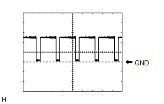
| Item | Content |
|---|---|
| Terminal No. | J43-6 (BLW) - J43-4 (GND) |
| Tool Setting | 2 V/DIV., 1 ms./DIV. |
| Vehicle Condition |
|
AIR CONDITIONING AMPLIFIER ASSEMBLY (w/ Rear Air Conditioning System)
HINT:
Check from the rear of the connector while it is connected to the air conditioning amplifier assembly.
| Terminal No. (Symbol) | Wiring Color | Terminal Description | Condition | Specified Condition |
|---|---|---|---|---|
| J42-1 (SG-1) - Body ground | L - Body ground | Ground for cooler (room temp. sensor) thermistor | Always | Below 1 V |
| J42-2 (SG-2) - Body ground | B - Body ground | Ground for cooler (ambient temp. sensor) thermistor, A/C lock sensor, smog ventilation sensor*2 | Always | Below 1 V |
| J42-3 (SG-4) - Body ground | BE - Body ground | Ground for air conditioner pressure sensor | Always | Below 1 V |
| J42-6 (S5-3) - J42-2 (SG-2) | W - B | Power supply for air conditioner pressure sensor | Engine switch on (IG) | 4.75 to 5.25 V |
| Engine switch off | Below 1 V | |||
| J42-9 (MGC) - J43-4 (GND) | R - W-B | Magnetic clutch operation signal |
| 11 to 14 V |
| Below 1 V | |||
| J42-10 (PTC2) - J43-4 (GND)*1 | G - W-B | Quick heater assembly operation signal |
| Below 1 V |
| 11 to 14 V | |||
| J42-11 (PTC3) - J43-4 (GND)*1 | Y - W-B | Quick heater assembly operation signal |
| Below 1 V |
| 11 to 14 V | |||
| J42-13 (TAM) - J42-2 (SG-2) | G - B | Cooler (ambient temp. sensor) thermistor signal |
| 1.35 to 1.75 V |
| 0.9 to 1.2 V | |||
| J42-14 (TR) - J42-1 (SG-1) | P - L | Cooler (room temp. sensor) thermistor signal |
| 1.8 to 2.2 V |
| 1.2 to 1.6 V | |||
| J42-20 (ECOS) - J43-4 (GND) | V - W-B | Combination switch assembly (ECO mode switch) signal |
| 11 to 14 V |
| Below 1 V | |||
| J42-21 (LOCK) - J42-2 (SG-2) | B - B | A/C lock sensor signal |
| Pulse generation (See waveform 1) |
| J42-24 (PRE) - J42-3 (SG-4) | L - BE | Air conditioner pressure sensor signal |
| 4.61 V or higher |
| Below 0.74 V | |||
| 0.74 to 4.61 V | |||
| J42-25 (DGS) - J42-2 (SG-2)*2 | LG - B | Smog ventilation sensor signal (HC, CO) | 28 seconds after engine switch turned on (IG) and sensor exposed to exhaust gas (HC, CO) | 1.0 to 4.5 V |
| J42-27 (DGS1) - J42-2 (SG-2)*2 | GR - B | Smog ventilation sensor signal (NOx) | 120 seconds after engine switch turned on (IG) and sensor exposed to exhaust gas (NOx) | 1.0 to 4.5 V |
| J43-1 (B) - J43-4 (GND) | R - W-B | Power source (Back-up) | Always | 11 to 14 V |
| J43-2 (IG+) - J43-4 (GND) | GR - W-B | Power source (IG) | Engine switch on (IG) | 11 to 14 V |
| Engine switch off | Below 1 V | |||
| J43-3 (SOL+) - J43-4 (GND) | SB - W-B | Compressor solenoid operation signal |
| Pulse generation (See waveform 2) |
| J43-4 (GND) - Body ground | W-B - Body ground | Ground for main power supply | Always | Below 1 V |
| J43-6 (BLW) - J43-4 (GND) | L - W-B | Blower motor speed control signal |
| Pulse generation (See waveform 3) |
| J43-11 (CANH) - J43-12 (CANL) | LG - W | CAN communication system | CAN communication is performed | Pulse generation |
| J43-16 (LIN3) - J43-4 (GND) | W - W-B | LIN communication signal | Engine switch on (IG) | Pulse generation |
| J43-18 (PTC1) - J43-4 (GND)*1 | LG - W-B | Quick heater assembly operation signal |
| Below 1 V |
| 11 to 14 V | |||
| J48-1 (GND2) - Body ground | W-B - Body ground | Ground for rear power supply | Always | Below 1 V |
| J48-2 (RBUG) - Body ground | GR - Body ground | Ground for BUS IC (for Rear side) | Always | Below 1 V |
| J48-3 (RBBU) - Body ground | LG - Body ground | Power supply for BUS IC (for Rear side) | Always | 11 to 14 V |
| J48-4 (+B2) - Body ground | L - Body ground | Rear power source (Back-up) | Always | 11 to 14 V |
| J48-6 (TR) - J48-20 (SG-7) | R - G | Cooler (No. 2 room temp. sensor) thermistor signal |
| 1.8 to 2.2 V |
| 1.2 to 1.6 V | |||
| J48-8 (TEC) - J48-21 (SG-8) | R - V | Rear evaporator temperature sensor signal |
| 2.0 to 2.4 V |
| 1.4 to 1.8 V | |||
| J48-12 (BLWH) - Body ground | V - Body ground | Rear blower motor speed control signal |
| Pulse generation (See waveform 4) |
| J48-20 (SG-7) - Body ground | G - Body ground | Ground for cooler (No. 2 room temp. sensor) thermistor | Always | Below 1 V |
| J48-21 (SG-8) - Body ground | V - Body ground | Ground for rear evaporator temperature sensor | Always | Below 1 V |
| J48-22 (RBUS) - J48-2 (RBUG) | SB - GR | BUS IC control signal (for Rear side) | Engine switch on (IG) | Pulse generation |
| z3-2 (BUS G) - Body ground | - | Ground for BUS IC (for Front side) | Always | Below 1 V |
| z3-3 (BUS) - z3-2 (BUS G) | - | BUS IC control signal (for Front side) | Engine switch on (IG) | Pulse generation |
| z3-4 (B BUS) - z3-2 (BUS G) | - | Power supply for BUS IC (for Front side) | Always | 11 to 14 V |
| z3-5 (SGA) - Body ground | - | Ground for No. 1 cooler thermistor | Always | Below 1 V |
| z3-6 (TEA) - z3-5 (SGA) | - | No. 1 cooler thermistor signal |
| 2.0 to 2.4 V |
| 1.4 to 1.8 V |
- *1: w/ PTC Heater
- *2: w/ Smog Ventilation Sensor
(a) Waveform 1:
| Item | Content |
|---|---|
| Terminal No. | J42-21 (LOCK) - J42-2 (SG-2) |
| Tool Setting | 200 mV/DIV., 10 ms./DIV. |
| Vehicle Condition |
|
(b) Waveform 2:
| Item | Content |
|---|---|
| Terminal No. | J43-3 (SOL+) - J43-4 (GND) |
| Tool Setting | 5 V/DIV., 500 μs./DIV. |
| Vehicle Condition |
|
(c) Waveform 3:
| Item | Content |
|---|---|
| Terminal No. | J43-6 (BLW) - J43-4 (GND) |
| Tool Setting | 2 V/DIV., 1 ms./DIV. |
| Vehicle Condition |
|
(d) Waveform 4:
| Item | Content |
|---|---|
| Terminal No. | J48-12 (BLWH) - Body ground |
| Tool Setting | 2 V/DIV., 500 μs./DIV. |
| Vehicle Condition |
|
NO. 2 AIR CONDITIONING CONTROL ASSEMBLY (w/ Rear Air Conditioning System)

HINT:
Check from the rear of the connector while it is connected to the No. 2 air conditioning control assembly.
| Terminal No. (Symbol) | Wiring Color | Terminal Description | Condition | Specified Condition |
|---|---|---|---|---|
| S90-2 (IG) - S90-4 (E) | LG - W-B | Power source (IG) | Engine switch on (IG) | 11 to 14 V |
| Engine switch off | Below 1 V | |||
| S90-4 (E) - Body ground | W-B - Body ground | Ground for No. 2 air conditioning control assembly | Always | Below 1 V |
| S90-6 (BLIN) - S90-4 (E) | G - W-B | LIN communication signal | Engine switch on (IG) | Pulse generation |
RADIO RECEIVER ASSEMBLY (A/C CONTROL PANEL)
w/ Navigation System: Click here .gif)
w/ Audio and Visual System (for 12.3 Inch Display): Click here
w/ Audio and Visual System (for 8 Inch Display): Click here
MULTI-DISPLAY ASSEMBLY
w/ Navigation System: Click here
w/ Audio and Visual System (for 12.3 Inch Display): Click here
w/ Audio and Visual System (for 8 Inch Display): Click here
 Diagnosis System
DIAGNOSIS SYSTEM DESCRIPTION Air conditioning system data and Diagnostic Trouble Codes (DTCs) can be read through the Data Link Connector 3 (DLC3) of the vehicle. When the system seems to be malfuncti ...
 Check Mode Procedure
CHECK MODE PROCEDURE REFRIGERANT SHORTAGE CHECK IN NORMAL OPERATION (CHECK A/C SWITCH INDICATOR AND DTC) (a) Start the engine. (b) Check that the A/C switch indicator remains on when the following con ...
Other materials:
Lexus RX (RX 350L, RX450h) 2016-2026 Repair Manual > Theft Deterrent System: Parts Location
PARTS LOCATION ILLUSTRATION *A w/ Security Horn Assembly - - *1 ENGINE HOOD COURTESY SWITCH *2 HIGH PITCHED HORN ASSEMBLY *3 HORN RELAY *4 LOW PITCHED HORN ASSEMBLY *5 SECURITY HORN ASSEMBLY *6 ENGINE ROOM RELAY BLOCK AND JUNCTION BLOCK ASSEMBLY - HORN FUSE ...
Lexus RX (RX 350L, RX450h) 2016-2026 Repair Manual > Road Sign Assist System: Data List / Active Test
DATA LIST / ACTIVE TEST DATA LIST NOTICE: In the table below, the values listed under "Normal Condition" are reference values. Do not depend solely on these reference values when deciding whether a part is faulty or not. HINT: Using the Techstream to read the Data List allows the values or states of ...
Lexus RX (RX 350L, RX450h) 2016-{YEAR} Owners Manual
- For your information
- Pictorial index
- For safety and security
- Instrument cluster
- Operation of each component
- Driving
- Lexus Display Audio system
- Interior features
- Maintenance and care
- When trouble arises
- Vehicle specifications
- For owners
Lexus RX (RX 350L, RX450h) 2016-{YEAR} Repair Manual

0.0097