Lexus RX (RX 350L, RX450h) 2016-2026 Repair Manual: Room Temperature Sensor Circuit (B1411/11)
DESCRIPTION
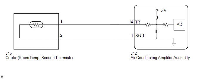
The cooler (room temp. sensor) thermistor is installed in the instrument panel to detect the cabin temperature, which is used to control the air conditioning system. The resistance of the cooler (room temp. sensor) thermistor changes in accordance with the cabin temperature. As the temperature decreases, the resistance increases. As the temperature increases, the resistance decreases.
The air conditioning amplifier assembly applies voltage (5 V) to the cooler (room temp. sensor) thermistor and reads voltage changes due to changes in the resistance of the cooler (room temp. sensor) thermistor.
| DTC No. | Detection Item | DTC Detection Condition | Trouble Area | Memory |
|---|---|---|---|---|
| B1411/11 | Room Temperature Sensor Circuit | Open or short in room temperature sensor circuit |
| Memorized (4 sec. or more)* |
- *: The air conditioning amplifier assembly stores this DTC if the malfunction has occurred for the period of time indicated in the brackets.
HINT:
If the cabin temperature is approximately -18.6°C (-1.48°F) or lower, DTC B1411/11 may be output even though the system is normal.
WIRING DIAGRAM
PROCEDURE
| 1. | READ VALUE USING TECHSTREAM |
(a) Connect the Techstream to the DLC3.
(b) Turn the engine switch on (IG).
(c) Turn the Techstream on.
(d) Enter the following menus: Body Electrical / Air Conditioner / Data List.
(e) Read the Data List according to the display on the Techstream.
Body Electrical > Air Conditioner > Data List| Tester Display | Measurement Item | Range | Normal Condition | Diagnostic Note |
|---|---|---|---|---|
| Room Temperature Sensor | Cooler (room temp. sensor) thermistor | Min.: -6.50°C (20.30°F) Max.: 57.25°C (135.05°F) | Actual cabin temperature displayed | - |
| Tester Display |
|---|
| Room Temperature Sensor |
OK:
The display is as specified in the normal condition column.
| Result | Proceed to |
|---|---|
| NG | A |
| OK (When troubleshooting according to Problem Symptoms Table) | B |
| OK (When troubleshooting according to the DTC) | C |
| B | .gif) | PROCEED TO NEXT SUSPECTED AREA SHOWN IN PROBLEM SYMPTOMS TABLE |
.gif)
| C | | REPLACE AIR CONDITIONING AMPLIFIER ASSEMBLY |
|
.gif)
| 2. | INSPECT COOLER (ROOM TEMP. SENSOR) THERMISTOR |
| (a) Remove the cooler (room temp. sensor) thermistor. Click here |
|
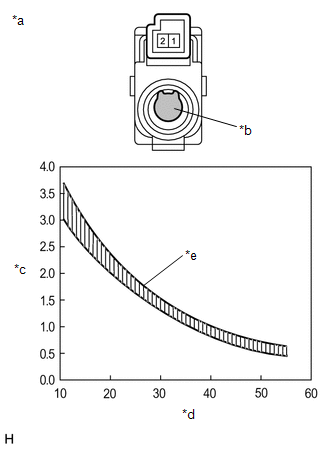
(b) Measure the resistance according to the value(s) in the table below.
Standard Resistance:
| Tester Connection | Condition | Specified Condition |
|---|---|---|
| 1 - 2 | 10°C (50°F) | 3.00 to 3.73 kΩ |
| 15°C (59°F) | 2.45 to 2.88 kΩ | |
| 20°C (68°F) | 1.95 to 2.30 kΩ | |
| 25°C (77°F) | 1.60 to 1.80 kΩ | |
| 30°C (86°F) | 1.28 to 1.47 kΩ | |
| 35°C (95°F) | 1.00 to 1.22 kΩ | |
| 40°C (104°F) | 0.80 to 1.00 kΩ | |
| 45°C (113°F) | 0.65 to 0.85 kΩ | |
| 50°C (122°F) | 0.50 to 0.70 kΩ | |
| 55°C (131°F) | 0.44 to 0.60 kΩ | |
| 60°C (140°F) | 0.36 to 0.50 kΩ |
NOTICE:
- Hold the sensor only by its connector. Touching the sensing portion may change the resistance value.
- When measuring, the sensor temperature must be the same as the ambient temperature.
HINT:
As the temperature increases, the resistance decreases (see the graph).
| NG | | REPLACE COOLER (ROOM TEMP. SENSOR) THERMISTOR |
|
| 3. | CHECK HARNESS AND CONNECTOR (COOLER (ROOM TEMP. SENSOR) THERMISTOR - AIR CONDITIONING AMPLIFIER ASSEMBLY) |
(a) Disconnect the J42 air conditioning amplifier assembly connector.
(b) Measure the resistance according to the value(s) in the table below.
Standard Resistance:
| Tester Connection | Condition | Specified Condition |
|---|---|---|
| J42-14 (TR) - J16-1 | Always | Below 1 Ω |
| J42-1 (SG-1) - J16-2 | Always | Below 1 Ω |
| J42-14 (TR) or J16-1 - Body ground | Always | 10 kΩ or higher |
| J42-1 (SG-1) or J16-2 - Body ground | Always | 10 kΩ or higher |
| OK | | REPLACE AIR CONDITIONING AMPLIFIER ASSEMBLY |
| NG | | REPAIR OR REPLACE HARNESS OR CONNECTOR |
 Data List / Active Test
DATA LIST / ACTIVE TEST DATA LIST NOTICE: In the table below, the values listed under "Normal Condition" are reference values. Do not depend solely on these reference values when deciding whether a pa ...
 Diagnostic Trouble Code Chart
DIAGNOSTIC TROUBLE CODE CHART Air Conditioning System DTC No. Detection Item DTC Detection Condition Link B1411/11 Room Temperature Sensor Circuit Open or short in room temperature se ...
Other materials:
Lexus RX (RX 350L, RX450h) 2016-2026 Repair Manual > Rear Power Outlet Socket (w/ Rear No. 2 Seat): Removal
REMOVAL PROCEDURE 1. REMOVE REAR NO. 2 SEAT ASSEMBLY Click here 2. REMOVE REAR DOOR SCUFF PLATE LH Click here 3. REMOVE REAR DOOR INSIDE SCUFF PLATE LH Click here 4. REMOVE REAR SEAT OUTER TRACK BRACKET COVER LH for 60/40 Split Seat Type: Click here for Captain Seat Type: Click here 5. ...
Lexus RX (RX 350L, RX450h) 2016-2026 Repair Manual > Sfi System: Throttle/Pedal Position Sensor/Switch "D" Circuit Voltage Out of Range (P21201C,P212099)
DESCRIPTION Refer to DTC P212012. Click here DTC No. Detection Item DTC Detection Condition Trouble Area MIL Memory Note P21201C Throttle/Pedal Position Sensor/Switch "D" Circuit Voltage Out of Range Difference between VPA and VPA2 is greater than or equal to the specified v ...
Lexus RX (RX 350L, RX450h) 2016-{YEAR} Owners Manual
- For your information
- Pictorial index
- For safety and security
- Instrument cluster
- Operation of each component
- Driving
- Lexus Display Audio system
- Interior features
- Maintenance and care
- When trouble arises
- Vehicle specifications
- For owners
Lexus RX (RX 350L, RX450h) 2016-{YEAR} Repair Manual

0.0227