Lexus RX (RX 350L, RX450h) 2016-2026 Repair Manual: Removal
REMOVAL
CAUTION / NOTICE / HINT
The necessary procedures (adjustment, calibration, initialization or registration) that must be performed after parts are removed and installed, or replaced during PTC heater assembly removal/installation are shown below.
Necessary Procedures after parts removed/installed/replaced| Replaced Part or Performed Procedure | Necessary Procedure | Effect/Inoperative Function when Necessary Procedure not Performed | Link |
|---|---|---|---|
|
*1: When performing learning using the Techstream.
Click here | |||
| Disconnect cable from negative battery terminal | Memorize steering angle neutral point | Lane Control System | |
| Pre-collision System | |||
| Intelligent Clearance Sonar System*1 | |||
| Parking Assist Monitor System | | ||
| Panoramic View Monitor System | | ||
| Lighting System (w/ Automatic Headlight Beam Level Control System) | | ||
| Initialize back door lock | Power Door Lock Control System | | |
| Reset back door close position | Power Back Door System (w/ Outside Door Control Switch) | | |
PROCEDURE
1. REMOVE LOWER NO. 1 INSTRUMENT PANEL AIRBAG ASSEMBLY
Click here .gif)
2. REMOVE CONSOLE BOX ASSEMBLY
Click here
3. REMOVE FRONT NO. 1 CONSOLE BOX INSERT
Click here
4. REMOVE NO. 4 AIR DUCT SUB-ASSEMBLY
Click here
5. REMOVE NO. 2 HEATER COVER
| (a) Remove the screw. |
|
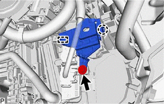
(b) Disengage the claw and guide to remove the No. 2 heater cover.
6. REMOVE QUICK HEATER ASSEMBLY
| (a) Disconnect the 2 connectors. |
|
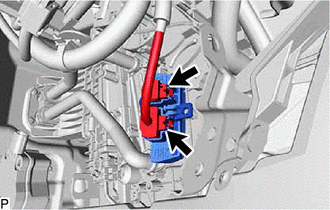
(b) Disengage the guide and remove the quick heater assembly as shown in the illustration.
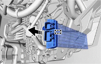
.png) | Remove in this Direction |
 Inspection
INSPECTION PROCEDURE 1. INSPECT QUICK HEATER ASSEMBLY (a) Measure the resistance according to the value(s) in the table below. Standard Resistance: Tester Connection Condition Specified Con ...
 Installation
INSTALLATION PROCEDURE 1. INSTALL QUICK HEATER ASSEMBLY (a) Engage the guide to install the quick heater assembly as shown in the illustration. Install in this Direction (b) Connect the 2 co ...
Other materials:
Lexus RX (RX 350L, RX450h) 2016-2026 Repair Manual > Navigation System: Panel Switches do not Function
CAUTION / NOTICE / HINT NOTICE: Depending on the parts that are replaced during vehicle inspection or maintenance, performing initialization, registration or calibration may be needed. Refer to Precaution for Navigation System. Click here PROCEDURE 1. CHECK PANEL SWITCH (a) Check for fore ...
Lexus RX (RX 350L, RX450h) 2016-2026 Repair Manual > Automatic Transaxle System: Transmission Fluid Temperature Sensor "A" Circuit Short to Battery or Open (P071015)
DESCRIPTION The ATF temperature sensor converts the automatic transaxle fluid (ATF) temperature into a resistance value for use by the ECM. The ECM applies voltage to the temperature sensor through terminal THO1 of the ECM. The sensor resistance changes with the ATF temperature. As the temperature r ...
Lexus RX (RX 350L, RX450h) 2016-{YEAR} Owners Manual
- For your information
- Pictorial index
- For safety and security
- Instrument cluster
- Operation of each component
- Driving
- Lexus Display Audio system
- Interior features
- Maintenance and care
- When trouble arises
- Vehicle specifications
- For owners
Lexus RX (RX 350L, RX450h) 2016-{YEAR} Repair Manual

0.0085