Lexus RX (RX 350L, RX450h) 2016-2026 Repair Manual: Removal
REMOVAL
CAUTION / NOTICE / HINT
The necessary procedures (adjustment, calibration, initialization or registration) that must be performed after parts are removed and installed, or replaced during solar sensor removal/installation are shown below.
Necessary Procedure After Parts Removed/Installed/Replaced| Replaced Part or Performed Procedure | Necessary Procedure | Effect/Inoperative Function when Necessary Procedure not Performed | Link |
|---|---|---|---|
|
*1: When performing learning using the Techstream.
Click here | |||
| Disconnect cable from negative battery terminal | Memorize steering angle neutral point | Lane Control System | |
| Pre-collision System | |||
| Intelligent Clearance Sonar System*1 | |||
| Parking Assist Monitor System | | ||
| Panoramic View Monitor System | | ||
| Lighting System (w/ Automatic Headlight Beam Level Control System) | | ||
| Initialize back door lock | Power Door Lock Control System | | |
| Reset back door close position | Power Back Door System (w/ Outside Door Control Switch) | | |
| Removal/installation of the spiral cable with sensor sub-assembly |
| Parking assist monitor system | |
| Steering angle neutral point (Initialize panoramic view monitor system) | Panoramic view monitor system | | |
| Steering angle neutral point (Initialize intelligent clearance sonar system) | Intelligent clearance sonar system | | |
PROCEDURE
1. REMOVE INSTRUMENT PANEL SAFETY PAD SUB-ASSEMBLY
Click here .gif)
2. REMOVE AUTOMATIC LIGHT CONTROL SENSOR
| (a) Disconnect the connector. |
|
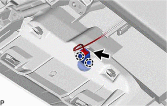
(b) Disengage the 2 claws to remove the automatic light control sensor.
 Components
COMPONENTS ILLUSTRATION *1 AUTOMATIC LIGHT CONTROL SENSOR - - ...
 Inspection
INSPECTION PROCEDURE 1. INSPECT AUTOMATIC LIGHT CONTROL SENSOR (a) Disconnect the K3 automatic light control sensor connector. *a Front view of wire harness connector (to Automatic L ...
Other materials:
Lexus RX (RX 350L, RX450h) 2016-2026 Repair Manual > Heated Steering Wheel System: Terminals Of Ecu
TERMINALS OF ECU STEERING WHEEL HEATER CONTROL ASSEMBLY HINT: Perform the inspection from the harness side with the connectors connected. (a) Measure the voltage or resistance according to the value(s) in the table below. Terminal No. (Symbol) Terminal Description Condition Specified Condi ...
Lexus RX (RX 350L, RX450h) 2016-2026 Repair Manual > Seat Heater System: Seat Heater for Front Right Seat does not Operate
DESCRIPTION When the refreshing seat switch (for front side) is operated, the air conditioning amplifier assembly receives the signal. The air conditioning amplifier assembly receives the signal and operates the front seat heater. WIRING DIAGRAM CAUTION / NOTICE / HINT NOTICE:
If the battery vol ...
Lexus RX (RX 350L, RX450h) 2016-{YEAR} Owners Manual
- For your information
- Pictorial index
- For safety and security
- Instrument cluster
- Operation of each component
- Driving
- Lexus Display Audio system
- Interior features
- Maintenance and care
- When trouble arises
- Vehicle specifications
- For owners
Lexus RX (RX 350L, RX450h) 2016-{YEAR} Repair Manual

0.0116