Lexus RX (RX 350L, RX450h) 2016-2026 Repair Manual: Disassembly
DISASSEMBLY
PROCEDURE
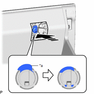
1. REMOVE HEADUP DISPLAY (METER MIRROR SUB-ASSEMBLY) (w/ Headup Display)
Click here .gif)
2. REMOVE INSTRUMENT PANEL PASSENGER AIRBAG ASSEMBLY
Click here
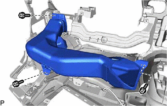
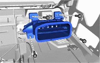
3. REMOVE NO. 1 HEATER TO REGISTER DUCT
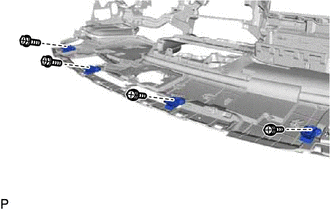
| (a) Remove the 3 screws <D> or <F> and No. 1 heater to register duct. |
|
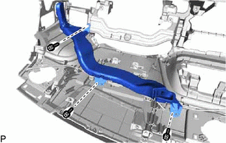
4. REMOVE NO. 4 HEATER TO REGISTER DUCT
| (a) Remove the 3 screws <D> or <F> and No. 4 heater to register duct. |
|
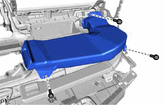
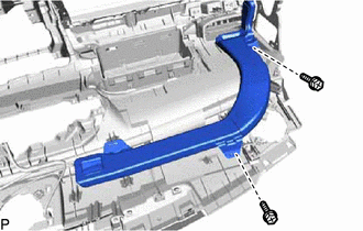
5. REMOVE DEFROSTER NOZZLE ASSEMBLY
| (a) Remove the 3 screws <D> or <F> and defroster nozzle assembly. |
|
6. REMOVE NO. 1 SIDE DEFROSTER NOZZLE DUCT
| (a) Remove the 3 screws <D> or <F> and No. 1 side defroster nozzle duct. |
|
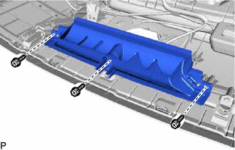
7. REMOVE NO. 2 SIDE DEFROSTER NOZZLE DUCT
| (a) Remove the 2 screws <D> or <F> and No. 2 side defroster nozzle duct |
|
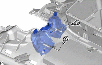
8. REMOVE NAVIGATION ANTENNA ASSEMBLY WITH BRACKET
Click here
9. REMOVE TELEPHONE AND GPS ANTENNA ASSEMBLY WITH BRACKET (w/ Manual (SOS) Switch)
Click here
10. REMOVE NO. 2 INSTRUMENT PANEL REGISTER ASSEMBLY
| (a) Remove the 4 screws <D> and No. 2 instrument panel register assembly. |
|
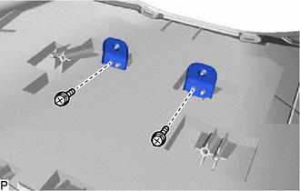
11. REMOVE NO. 1 METER HOOD RETAINER
| (a) Remove the 2 screws <D> and 2 No. 1 meter hood retainers. |
|
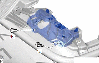
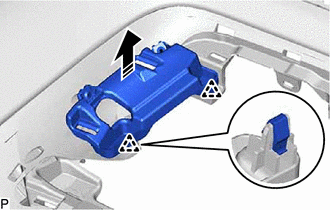
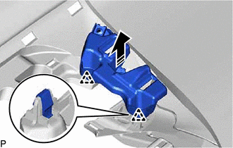
12. REMOVE AUTOMATIC LIGHT CONTROL SENSOR
Click here
13. REMOVE NO. 1 DEFROSTER NOZZLE GARNISH
(a) Disengage the 7 claws, 5 clips and 2 guides.
(b) Disengage the 7 guides to remove the No. 1 defroster nozzle garnish.
14. REMOVE ANTENNA CORD SUB-ASSEMBLY
w/o Rear No. 2 Seat:
Click here
w/ Rear No. 2 Seat:
Click here
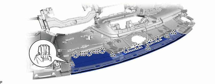
15. REMOVE NO. 2 INSTRUMENT PANEL WIRE
| (a) Disengage the 10 clamps to remove the No. 2 instrument panel wire. |
|
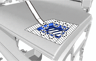
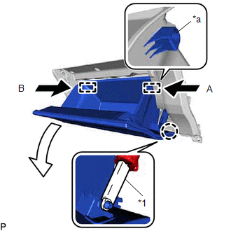
16. REMOVE NO. 1 SIDE DEFROSTER NOZZLE
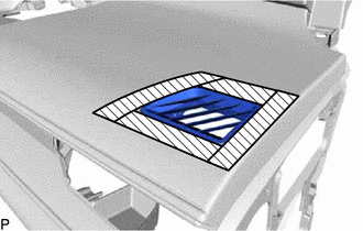
(a) Apply protective tape to the areas shown in the illustration.
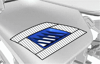
.png) | Protective Tape |
| (b) Using a moulding remover A, disengage the 6 claws to remove the No. 1 side defroster nozzle. |
|
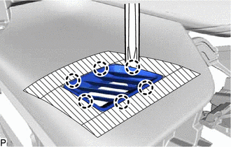
17. REMOVE NO. 2 SIDE DEFROSTER NOZZLE
(a) Apply protective tape to the areas shown in the illustration.
| | Protective Tape |
| (b) Using a moulding remover A, disengage the 6 claws to remove the No. 2 side defroster nozzle. |
|
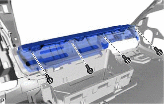
18. REMOVE NO. 1 INSTRUMENT PANEL SAFETY PAD SUB-ASSEMBLY (for TMMC Made)
| (a) Remove the 4 screws <D>. |
|
(b) Disengage the 3 clips to remove the No. 1 instrument panel safety pad sub-assembly as shown in the illustration.
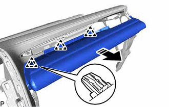
.png) | Remove in this Direction |
19. REMOVE NO. 1 INSTRUMENT PANEL PIN
| (a) Remove the 4 screws <D> or <E> and 4 No. 1 instrument panel pins. |
|
20. REMOVE NO. 2 RADIO TUNER OPENING RETAINER (for TMMC Made)
| (a) Remove the screw <D> and bolt <H>. |
|
(b) Disengage the 2 clips to remove the No. 2 radio tuner opening retainer as shown in the illustration.
| | Remove in this Direction |
21. REMOVE NO. 1 RADIO TUNER OPENING RETAINER (for TMMC Made)
| (a) Remove the 2 screws <D>. |
|
(b) Disengage the 2 clips to remove the No. 1 radio tuner opening retainer as shown in the illustration.
| | Remove in this Direction |
22. REMOVE INSTRUMENT CLUSTER FINISH PANEL RETAINER (for TMMC Made)
| (a) Remove the 7 screws <D>. |
|
| (b) Disengage the 4 claws to remove the instrument cluster finish panel retainer. |
|
23. REMOVE GLOVE COMPARTMENT DOOR LOCK CYLINDER ASSEMBLY
NOTICE:
Perform this procedure only when replacement of the glove compartment door assembly is necessary.
| (a) Disengage the claw to disconnect the glove compartment door stopper sub-assembly. |
|
(b) Slightly bend stoppers (A) and (B) in the directions indicated by the arrows shown in the illustration and open the glove compartment door assembly until the stoppers are released.
(c) Open the glove compartment door assembly to approximately 52.5° from its closed position. Pull it horizontally in the direction indicated by the arrow shown in the illustration to disengage the 2 hinges and remove the glove compartment door assembly.
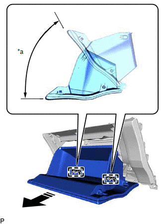
| *a | 52.5° |
| | Remove in this Direction |
NOTICE:
Pulling the glove compartment door assembly upward when removing it will cause the hinges to deform. Be sure to pull out the glove compartment door assembly horizontally.
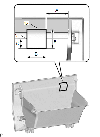
| (d) Mark the glove compartment door assembly as shown in the illustration. Standard Measurement
|
|
(e) Insert a 3.0 mm (0.118 in.) drill bit into a drill.
(f) Tape the 3.0 mm (0.118 in.) drill bit 10.0 mm (0.394 in.) from the tip as shown in the illustration.
NOTICE:
Tape the 3.0 mm (0.118 in.) drill bit to prevent the drill bit from going too deep.
(g) Drill holes along the marking as shown in the illustration.
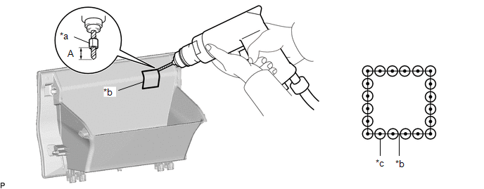
| *a | Tape | *b | Marking |
| *c | Drilled Hole | - | - |
| Area | Area |
|---|---|
| A | 10.0 mm (0.394 in.) |
CAUTION:
- In order to avoid injury, make sure to work carefully so that the tip of the drill does not slip.
- Make sure to wear protective glasses when performing this procedure as shavings will fly about.
NOTICE:
To prevent the glove compartment door lock cylinder assembly from being damaged, make sure to only drill holes along the marking.
(h) Insert a 7.0 mm (0.276 in.) drill bit into a drill.
(i) Tape the 7.0 mm (0.276 in.) drill bit 10.0 mm (0.394 in.) from the tip as shown in the illustration.
NOTICE:
Tape the 7.0 mm (0.276 in.) drill bit to prevent the drill bit from going too deep.
(j) Redrill each hole using the 7.0 mm (0.276 in.) drill bit.
CAUTION:
- In order to avoid injury, make sure to center the tip of the drill in the pilot hole so that the tip of the drill does not slip.
- Make sure to wear protective glasses when performing this procedure as shavings will fly about.
(k) Using a plier nipper (side cutters), cut the glove compartment door assembly between each hole.
(l) Move the arm as shown in the illustration.
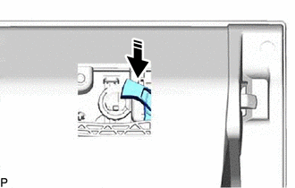
| | Move in this Direction |
(m) Press the cylinder lock to release it and pull out the glove compartment door lock cylinder assembly from the glove compartment door assembly to remove it as shown in the illustration.
| *a | Cylinder Lock |
| | Remove in this Direction |
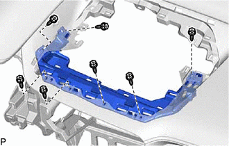
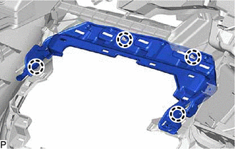
 Components
COMPONENTS ILLUSTRATION *1 COMBINATION METER ASSEMBLY *2 COWL SIDE TRIM BOARD LH *3 FRONT DOOR SCUFF PLATE LH *4 HOOD LOCK CONTROL LEVER SUB-ASSEMBLY *5 INSTRUMENT CLUSTER FI ...
 Reassembly
REASSEMBLY PROCEDURE 1. INSTALL GLOVE COMPARTMENT DOOR LOCK CYLINDER ASSEMBLY (a) With the cylinder lock pressed, insert the glove compartment door lock cylinder assembly into the glove compartment do ...
Other materials:
Lexus RX (RX 350L, RX450h) 2016-2026 Repair Manual > Camshaft Position Sensor: Removal
REMOVAL CAUTION / NOTICE / HINT The necessary procedures (adjustment, calibration, initialization or registration) that must be performed after parts are removed and installed, or replaced during camshaft position sensor removal/installation are shown below. Necessary Procedures After Parts Removed/ ...
Lexus RX (RX 350L, RX450h) 2016-2026 Repair Manual > Brake Pedal: Reassembly
REASSEMBLY PROCEDURE 1. INSTALL BRAKE PEDAL PAD (a) Install the brake pedal pad to the brake pedal sub-assembly. 2. INSTALL BRAKE PEDAL BUSHING (a) Apply lithium soap base glycol grease to 2 new brake pedal bushings. Lithium Soap Base Glycol Grease (b) Install the 2 brake pedal bushings to ...
Lexus RX (RX 350L, RX450h) 2016-{YEAR} Owners Manual
- For your information
- Pictorial index
- For safety and security
- Instrument cluster
- Operation of each component
- Driving
- Lexus Display Audio system
- Interior features
- Maintenance and care
- When trouble arises
- Vehicle specifications
- For owners
Lexus RX (RX 350L, RX450h) 2016-{YEAR} Repair Manual

0.0092