Lexus RX (RX 350L, RX450h) 2016-2026 Repair Manual: Reassembly
REASSEMBLY
PROCEDURE
1. INSTALL GLOVE COMPARTMENT DOOR LOCK CYLINDER ASSEMBLY
(a) With the cylinder lock pressed, insert the glove compartment door lock cylinder assembly into the glove compartment door assembly to install it as shown in the illustration.
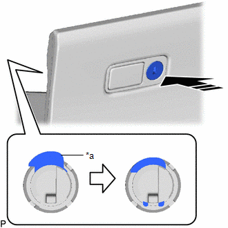
| *a | Cylinder Lock |
.png) | Install in this Direction |
(b) for TMC Made:
(1) With the glove compartment door assembly opened approximately 52.5° from its closed position, engage the 2 hinges horizontally.
NOTICE:
Engaging the hinges from an upward angle will deform the hinges. Be sure to install the glove compartment door assembly horizontally.

| *a | 52.5° |
| | Install in this Direction |
| (2) Slightly bend the stoppers (A) and (B) in the directions indicated by the arrows shown in the illustration and engage the stoppers to install the glove compartment door assembly. |
|
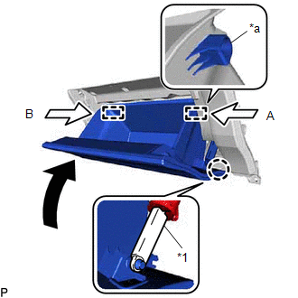
(3) Engage the claw to connect the glove compartment door stopper sub-assembly.
2. INSTALL INSTRUMENT CLUSTER FINISH PANEL RETAINER (for TMMC Made)
| (a) Engage the 4 claws. |
|
.png)
| (b) Install the instrument cluster finish panel retainer with the 7 screws <D>. |
|
.png)
3. INSTALL NO. 1 RADIO TUNER OPENING RETAINER (for TMMC Made)
(a) Engage the 2 clips as shown in the illustration.
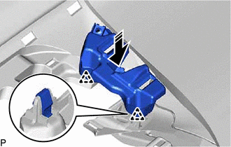
| | Install in this Direction |
| (b) Install the No. 1 radio tuner opening retainer with the 2 screws <D>. |
|
.png)
4. INSTALL NO. 2 RADIO TUNER OPENING RETAINER (for TMMC Made)
(a) Engage the 2 clips as shown in the illustration.
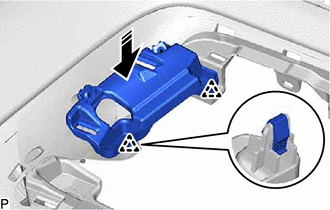
| | Install in this Direction |
| (b) Install the No. 2 radio tuner opening retainer with the screw <D> and bolt <H>. |
|
.png)
5. INSTALL NO. 1 INSTRUMENT PANEL PIN
| (a) Install the 4 No. 1 instrument panel pins with the 4 screws <D> or <E>. |
|
.png)
6. INSTALL NO. 1 INSTRUMENT PANEL SAFETY PAD SUB-ASSEMBLY (for TMMC Made)
(a) Engage the 3 clips as shown in the illustration.
| | Install in this Direction |
| (b) Install the No. 1 instrument panel safety pad sub-assembly with the 4 screws <D>. |
|
.png)
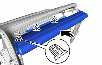
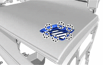
7. INSTALL NO. 2 SIDE DEFROSTER NOZZLE
| (a) Engage the 6 claws to install the No. 2 side defroster nozzle. |
|
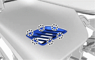
8. INSTALL NO. 1 SIDE DEFROSTER NOZZLE
| (a) Engage the 6 claws to install the No. 1 side defroster nozzle. |
|
9. INSTALL NO. 2 INSTRUMENT PANEL WIRE
| (a) Engage the 10 clamps to install the No. 2 instrument panel wire. |
|
.png)
10. INSTALL ANTENNA CORD SUB-ASSEMBLY
w/o Rear No. 2 Seat:
Click here .gif)
w/ Rear No. 2 Seat:
Click here
11. INSTALL NO. 1 DEFROSTER NOZZLE GARNISH
(a) Engage the 7 guides.
.png)
(b) Engage the 2 guides, 5 clips and 7 claws to install the No. 1 defroster nozzle garnish.
.png)
12. INSTALL AUTOMATIC LIGHT CONTROL SENSOR
Click here
13. INSTALL NO. 1 METER HOOD RETAINER
| (a) Install the 2 No. 1 meter hood retainers with the 2 screws <D>. |
|
.png)
14. INSTALL NO. 2 INSTRUMENT PANEL REGISTER ASSEMBLY
| (a) Install the No. 2 instrument panel register assembly with the 4 screws <D>. |
|
.png)
15. INSTALL NAVIGATION ANTENNA ASSEMBLY WITH BRACKET
Click here
16. INSTALL TELEPHONE AND GPS ANTENNA ASSEMBLY WITH BRACKET (w/ Manual (SOS) Switch)
Click here
17. INSTALL NO. 2 SIDE DEFROSTER NOZZLE DUCT
| (a) Install the No. 2 side defroster nozzle duct with the 2 screws <D> or <F>. |
|
.png)
18. INSTALL NO. 1 SIDE DEFROSTER NOZZLE DUCT
| (a) Install the No. 1 side defroster nozzle duct with the 3 screws <D> or <F>. |
|
.png)
19. INSTALL DEFROSTER NOZZLE ASSEMBLY
| (a) Install the defroster nozzle assembly with the 3 screws <D> or <F>. |
|
.png)
20. INSTALL NO. 4 HEATER TO REGISTER DUCT
| (a) Install the No. 4 heater to register duct with the 3 screws <D> or <F>. |
|
.png)
21. INSTALL NO. 1 HEATER TO REGISTER DUCT
| (a) Install the No. 1 heater to register duct with the 3 screws <D> or <F>. |
|
.png)
22. INSTALL INSTRUMENT PANEL PASSENGER AIRBAG ASSEMBLY
Click here
23. INSTALL HEADUP DISPLAY (METER MIRROR SUB-ASSEMBLY) (w/ Headup Display)
Click here
 Disassembly
DISASSEMBLY PROCEDURE 1. REMOVE HEADUP DISPLAY (METER MIRROR SUB-ASSEMBLY) (w/ Headup Display) Click here 2. REMOVE INSTRUMENT PANEL PASSENGER AIRBAG ASSEMBLY Click here 3. REMOVE NO. 1 HEATER TO ...
 Removal
REMOVAL CAUTION / NOTICE / HINT The necessary procedures (adjustment, calibration, initialization or registration) that must be performed after parts are removed and installed, or replaced during inst ...
Other materials:
Lexus RX (RX 350L, RX450h) 2016-2026 Repair Manual > Lighting System (w/ Automatic Headlight Beam Level Control System): Steering Position Sensor (B2414)
DESCRIPTION The No. 1 headlight ECU sub-assembly LH receives steering angle signals from the steering sensor via CAN communication and performs light control. DTC No. Detection Item DTC Detection Condition Trouble Area DTC Output from B2414 Steering Position Sensor
The engine s ...
Lexus RX (RX 350L, RX450h) 2016-2026 Repair Manual > Rear Power Seat Control System(for Third Row): Power Seat Motor Circuit
DESCRIPTION When a switch of the fold seat switch assembly or No. 1 fold seat switch assembly is pushed, the fold seat control ECU receives a switch operation signal and operates each motor. WIRING DIAGRAM CAUTION / NOTICE / HINT NOTICE:
When a fold seat control ECU (RH/LH seat) is replaced, it ...
Lexus RX (RX 350L, RX450h) 2016-{YEAR} Owners Manual
- For your information
- Pictorial index
- For safety and security
- Instrument cluster
- Operation of each component
- Driving
- Lexus Display Audio system
- Interior features
- Maintenance and care
- When trouble arises
- Vehicle specifications
- For owners
Lexus RX (RX 350L, RX450h) 2016-{YEAR} Repair Manual

0.0123