Lexus RX (RX 350L, RX450h) 2016-2026 Repair Manual: Removal
REMOVAL
CAUTION / NOTICE / HINT
The necessary procedures (adjustment, calibration, initialization or registration) that must be performed after parts are removed and installed, or replaced during instrument panel safety pad removal/installation are shown below.
Necessary Procedures After Parts Removed/Installed/Replaced| Replaced Part or Performed Procedure | Necessary Procedure | Effect/Inoperative Function when Necessary Procedure not Performed | Link |
|---|---|---|---|
| Disconnect cable from negative battery terminal | Memorize steering angle neutral point | Lane Control System | |
| Pre-collision system | |||
| Intelligent clearance sonar system*1 | |||
| Parking Assist Monitor System | | ||
| Panoramic View Monitor System | | ||
| Lighting System (w/ Automatic Headlight Beam Level Control System) | | ||
| Initialize back door lock | Power door lock control system | | |
| Reset back door close position | Power Back Door System (w/ Outside Door Control Switch) | | |
| Removal/installation of the spiral cable with sensor sub-assembly |
| Parking assist monitor system | |
| Steering angle neutral point (Initialize panoramic view monitor system) | Panoramic view monitor system | | |
| Steering angle neutral point (Initialize intelligent clearance sonar system) |
| |
*1: When performing learning using the Techstream.
Click here .gif)
CAUTION:
Some of these service operations affect the SRS airbag system. Read the precautionary notices concerning the SRS airbag system before servicing.
Click here
PROCEDURE
1. PRECAUTION
Click here
NOTICE:
After turning the engine switch off, waiting time may be required before disconnecting the cable from the negative (-) battery terminal. Therefore, make sure to read the disconnecting the cable from the negative (-) battery terminal notices before proceeding with work.
Click here
2. REMOVE HEADLIGHT DIMMER SWITCH ASSEMBLY
Click here
3. REMOVE CONSOLE BOX ASSEMBLY
Click here
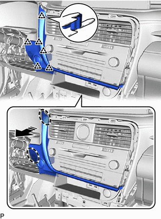
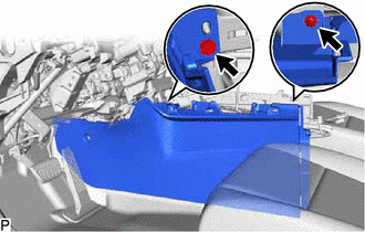
4. REMOVE INSTRUMENT PANEL GARNISH LH
(a) except TMMC Made:
(1) Using a moulding remover B, disengage the 8 clips to remove the instrument panel garnish LH as shown in the illustration.
.png) | Remove in this Direction |
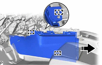
(b) for TMMC Made:
(1) Using a moulding remover B, disengage the 9 clips to remove the instrument panel garnish LH as shown in the illustration.
| | Remove in this Direction |
5. REMOVE FRONT DOOR SCUFF PLATE LH
Click here
6. REMOVE COWL SIDE TRIM BOARD LH
Click here
7. REMOVE NO. 1 INSTRUMENT PANEL UNDER COVER SUB-ASSEMBLY
| (a) Remove the 2 screws <D>. |
|
(b) Disengage the 3 claws as shown in the illustration.
| | Remove in this Direction |
(c) Disengage the 2 guides as shown in the illustration.
| | Remove in this Direction |
| (d) Disengage the 2 claws to disconnect the DLC3 connector. |
|
(e) Disconnect the connector.
(f) Disengage the clamp to remove the No. 1 instrument panel under cover sub-assembly.
8. DISCONNECT HOOD LOCK CONTROL LEVER SUB-ASSEMBLY
| (a) Disengage the claw and 2 guides to disconnect the hood lock control lever sub-assembly. |
|
9. REMOVE LOWER INSTRUMENT PANEL FINISH PANEL SUB-ASSEMBLY
| (a) Using a screwdriver with its tip wrapped with protective tape, disengage the 2 claws to disconnect the instrument panel hole cover. |
|
| (b) Remove the 2 screws <D>. |
|
(c) Disengage the 11 clips and 3 claws as shown in the illustration.
| | Remove in this Direction |
(d) Disconnect each connector to remove the lower instrument panel finish panel sub-assembly.
10. REMOVE LOWER INSTRUMENT FINISH PANEL SUB
(a) Disengage the 3 clips and 4 guides as shown in the illustration.
.png) | Place Hand Here |
| | Remove in this Direction |
.png) | Order of Removal |
(b) Disengage the 6 clips as shown in the illustration.
| | Place Hand Here |
| | Remove in this Direction |
(c) Disconnect the connector to remove the lower instrument finish panel sub.
11. REMOVE LOWER NO. 1 INSTRUMENT PANEL AIRBAG ASSEMBLY
Click here
12. REMOVE INSTRUMENT CLUSTER FINISH PANEL SUB-ASSEMBLY
(a) Disengage the 4 clips as shown in the illustration.
| | Place Hand Here |
| | Remove in this Direction |
(b) Disengage the 3 clips as shown in the illustration.
| | Place Hand Here |
| | Remove in this Direction |
(c) Disconnect the connector to remove the instrument cluster finish panel sub-assembly.
13. REMOVE COMBINATION METER ASSEMBLY
Click here
14. REMOVE COOLER (ROOM TEMP. SENSOR) THERMISTOR
Click here
15. REMOVE RADIO RECEIVER ASSEMBLY WITH REGISTER
Click here
16. REMOVE CONSOLE BOX ASSEMBLY
| (a) Disengage the clamp. |
|
(b) Disengage the 5 clips as shown in the illustration.
| | Place Hand Here |
| | Remove in this Direction |
(c) Disconnect each connector to remove the console box assembly.
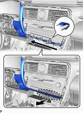
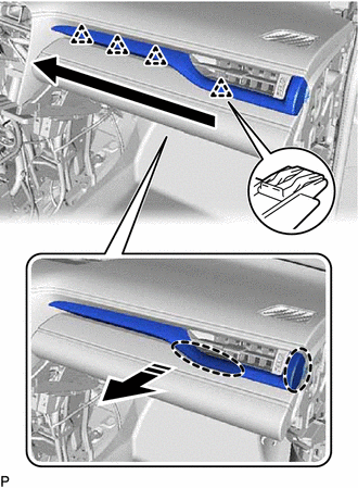
17. REMOVE INSTRUMENT PANEL FINISH PANEL SUB-ASSEMBLY
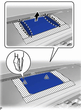
(a) Apply protective tape to the areas shown in the illustration.
.png) | Protective Tape |
(b) Using a moulding remover A, disengage the 2 clips as shown in the illustration.
| | Insert Moulding Remover A Here |
| | Remove in this Direction |
(c) Using a moulding remover A, disengage the 2 clips as shown in the illustration.
| | Insert Moulding Remover A Here |
| | Remove in this Direction |
(d) Disengage the 4 clips and 8 guides to remove the instrument panel finish panel sub-assembly as shown in the illustration.
| | Remove in this Direction |
18. REMOVE MULTI-DISPLAY ASSEMBLY
Click here
19. REMOVE CENTER INSTRUMENT CLUSTER FINISH PANEL SUB-ASSEMBLY
(a) Apply protective tape to the areas shown in the illustration.
| | Protective Tape |
(b) Using a moulding remover B, disengage the 10 clips as shown in the illustration.

| | Remove in this Direction |
(c) Disengage the 5 guides to remove the center instrument cluster finish panel sub-assembly as shown in the illustration.
| | Remove in this Direction (1) |
.png) | Remove in this Direction (2) |
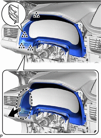
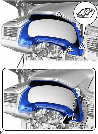
20. REMOVE INSTRUMENT PANEL GARNISH RH
(a) except TMMC Made:
(1) Using a moulding remover B, disengage the 8 clips to remove the instrument panel garnish RH as shown in the illustration.
| | Remove in this Direction |
(b) for TMMC Made:
(1) Using a moulding remover B, disengage the 9 clips to remove the instrument panel garnish RH as shown in the illustration.
| | Remove in this Direction |
21. REMOVE FRONT DOOR SCUFF PLATE RH
HINT:
Use the same procedure as for the LH side.
22. REMOVE COWL SIDE TRIM BOARD RH
HINT:
Use the same procedure as for the LH side.
23. REMOVE NO. 2 INSTRUMENT PANEL UNDER COVER SUB-ASSEMBLY
| (a) Remove the 2 screws <D>. |
|
(b) Disengage the 2 claws as shown in the illustration.
| | Remove in this Direction |
(c) Disengage the 2 guides as shown in the illustration.
| | Remove in this Direction |
(d) Disconnect the connector to remove the No. 2 instrument panel under cover sub-assembly.
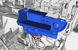
24. REMOVE GLOVE COMPARTMENT DOOR ASSEMBLY
(a) Open the glove compartment door assembly.
| (b) Remove the 3 screws <E>. |
|
(c) Close the glove compartment door assembly.
| (d) Remove the 2 bolts <B> or <C>. |
|
(e) Disengage the 6 claws as shown in the illustration.
| | Remove in this Direction |
(f) Disconnect the connector.
(g) Disengage the clamp to remove the glove compartment door assembly.
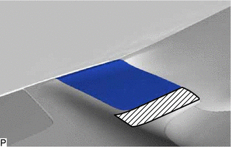
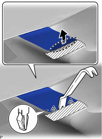
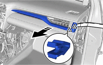
25. REMOVE NO. 1 INSTRUMENT PANEL SPEAKER PANEL SUB-ASSEMBLY
(a) Apply protective tape to the area shown in the illustration.
| | Protective Tape |
(b) Using a moulding remover B, disengage the 2 clips as shown in the illustration.
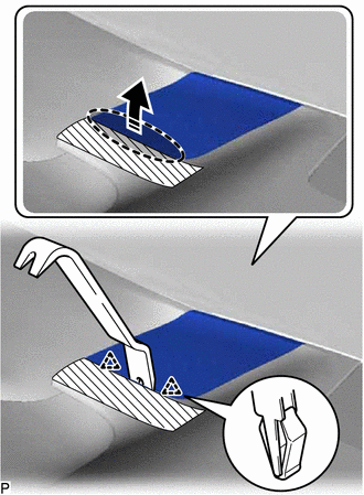
| | Insert Moulding Remover B Here |
| | Remove in this Direction |
(c) Disengage the 2 guides to remove the No. 1 instrument panel speaker panel sub-assembly as shown in the illustration.
| | Remove in this Direction |
26. REMOVE FRONT NO. 2 SPEAKER ASSEMBLY (for LH Side)
Click here
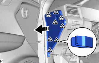
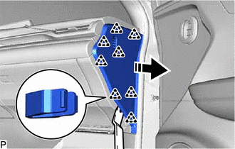
27. REMOVE FRONT PILLAR GARNISH LH
Click here
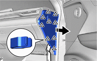
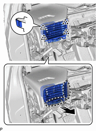
28. REMOVE NO. 1 SPEAKER OPENING COVER ASSEMBLY
(a) Apply protective tape to the areas shown in the illustration.
| | Protective Tape |
(b) Using a moulding remover B, disengage the 2 clips as shown in the illustration.
| | Insert Moulding Remover B Here |
| | Remove in this Direction |
(c) Disengage the 2 clips to remove the No. 1 speaker opening cover assembly as shown in the illustration.
| | Place Hand Here |
| | Remove in this Direction |
29. REMOVE FRONT NO. 3 SPEAKER ASSEMBLY
Click here
30. REMOVE NO. 2 INSTRUMENT PANEL SPEAKER PANEL SUB-ASSEMBLY
(a) Apply protective tape to the area shown in the illustration.
| | Protective Tape |
(b) Using a moulding remover B, disengage the 2 clips as shown in the illustration.
| | Insert Moulding Remover B Here |
| | Remove in this Direction |
(c) Disengage the 2 guides to remove the No. 2 instrument panel speaker panel sub-assembly as shown in the illustration.
| | Remove in this Direction |
31. REMOVE FRONT NO. 2 SPEAKER ASSEMBLY (for RH Side)
HINT:
Use the same procedure as for the LH side.
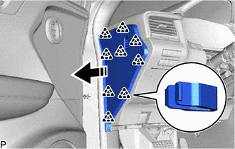
32. REMOVE FRONT PILLAR GARNISH RH
HINT:
Use the same procedure as for the LH side.
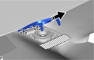
33. REMOVE NO. 1 INSTRUMENT PANEL REGISTER ASSEMBLY
(a) Disengage the 4 clips to remove the No. 1 instrument panel register assembly as shown in the illustration.
| | Place Hand Here |
| | Remove in this Direction |
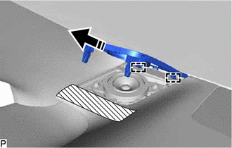
34. REMOVE NO. 2 INSTRUMENT CLUSTER MOULDING
(a) Using a moulding remover A, disengage the 2 clips as shown in the illustration.
| | Remove in this Direction |
(b) Disengage the 4 clips to remove the No. 2 instrument cluster moulding as shown in the illustration.
| | Place Hand Here |
| | Remove in this Direction |
| | Order of Removal |
(c) w/ Interior Illumination:
(1) Disconnect the connector.
35. REMOVE FRONT NO. 1 CONSOLE BOX INSERT
| (a) Using a clip remover, remove the clip. |
|
| (b) Remove the 2 screws <E>. |
|
(c) Disengage the 3 guides to remove the front No. 1 console box insert as shown in the illustration.
| | Remove in this Direction |
36. REMOVE FRONT NO. 2 CONSOLE BOX INSERT
| (a) Using a clip remover, remove the clip. |
|
| (b) Remove the 4 screws <E>. |
|
(c) Disengage the guide to remove the front No. 2 console box insert as shown in the illustration.
| | Remove in this Direction |
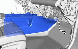
37. DISCONNECT NO. 2 INSTRUMENT PANEL WIRE
Click here
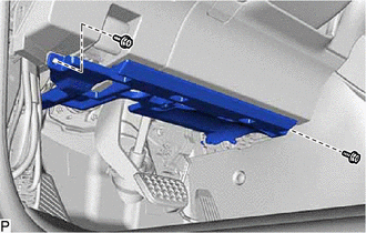
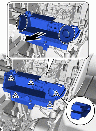
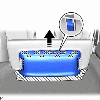
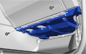
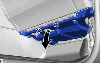
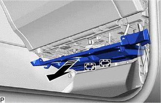
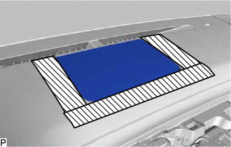
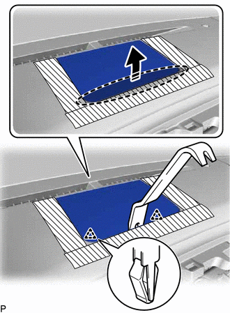
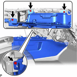
38. REMOVE INSTRUMENT PANEL SAFETY PAD SUB-ASSEMBLY
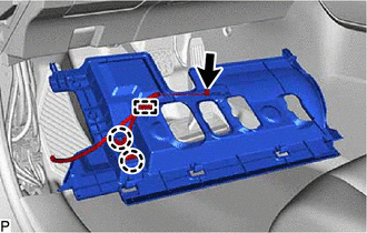
(a) Disconnect each connector.
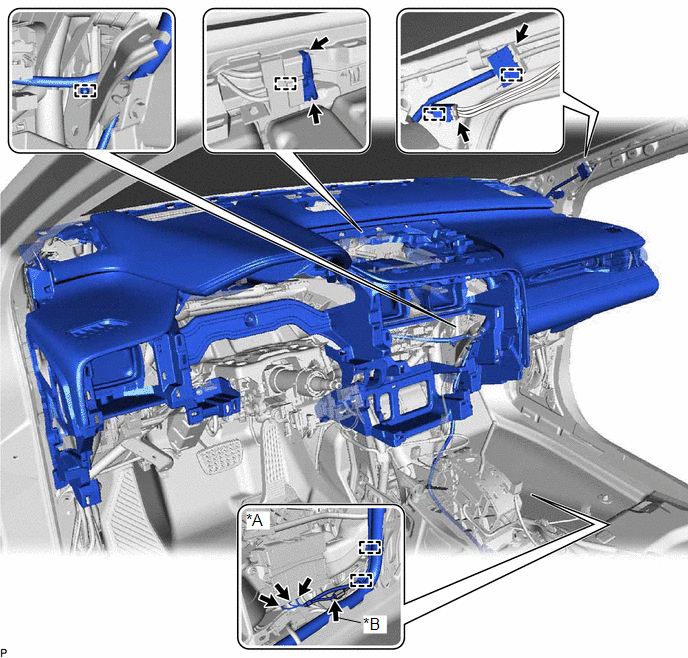
| *A | w/ Telematics Transceiver | *B | w/ Rear No. 2 Seat |
(b) Disengage each clamp.
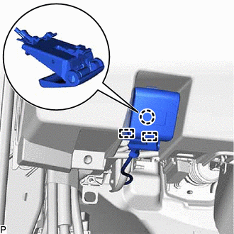
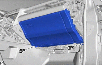
(c) Remove the 2 clips.
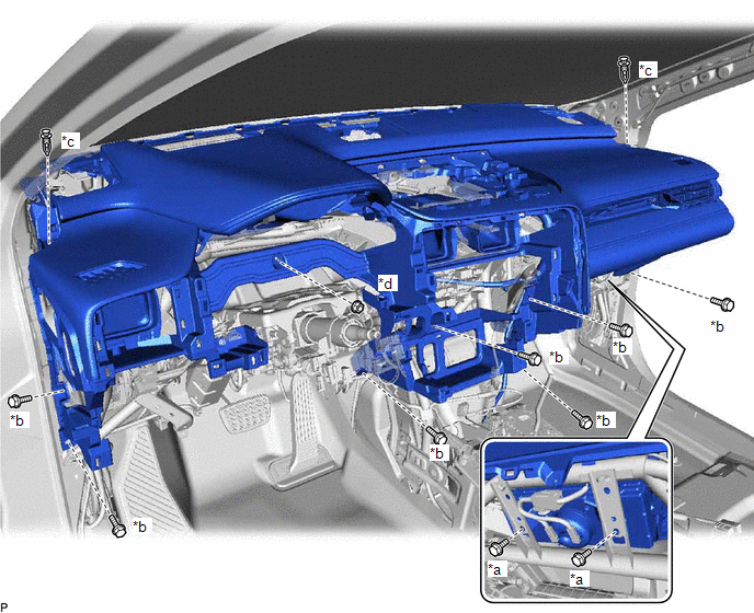
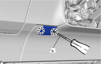
| *a | Bolt <A> | *b | Bolt <C> |
| *c | Clip | *d | Nut <G> |
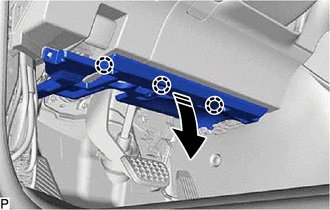
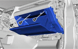
(d) Remove the 7 bolts <C>, 2 bolts <A> and nut <G>.
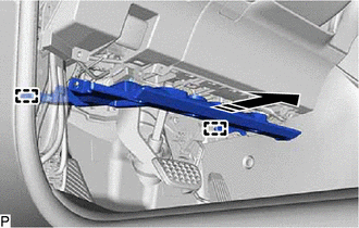
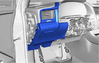
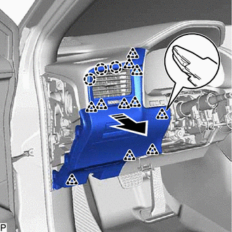
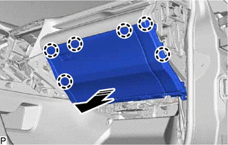
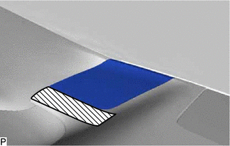
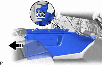
(e) Disengage the 4 guides and remove the instrument panel safety pad sub-assembly as shown in the illustration.
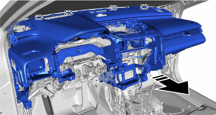
| | Remove in this Direction | - | - |
NOTICE:
- Do not damage the instrument panel safety pad sub-assembly.
- Do not allow the wire harnesses to interfere with the surrounding parts.
 Reassembly
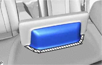
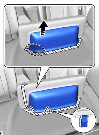
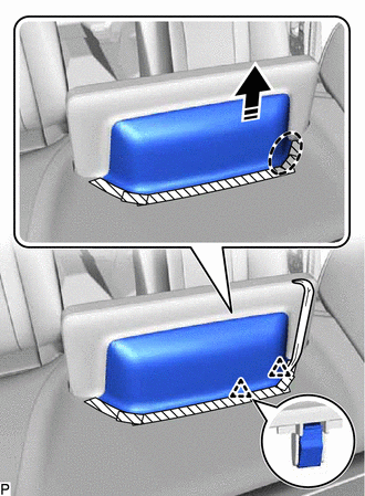
REASSEMBLY PROCEDURE 1. INSTALL GLOVE COMPARTMENT DOOR LOCK CYLINDER ASSEMBLY (a) With the cylinder lock pressed, insert the glove compartment door lock cylinder assembly into the glove compartment do ...
 Installation
INSTALLATION PROCEDURE 1. INSTALL INSTRUMENT PANEL SAFETY PAD SUB-ASSEMBLY (a) Engage the 4 guides to temporarily install the instrument panel safety pad sub-assembly as shown in the illustration. ...
Other materials:
Lexus RX (RX 350L, RX450h) 2016-2026 Repair Manual > Headlight Assembly: Adjustment
ADJUSTMENT CAUTION / NOTICE / HINT HINT:
Use the same procedure for the RH side and LH side.
The following procedure is for the LH side.
PROCEDURE 1. PREPARE VEHICLE FOR HEADLIGHT AIM ADJUSTMENT (a) Prepare the vehicle:
Ensure that there is no damage or deformation to the vehicle body aro ...
Lexus RX (RX 350L, RX450h) 2016-2026 Repair Manual > Sfi System: Internal Control Module Accelerator Pedal Position Performance Internal Electronic Failure (P060D49)
MONITOR DESCRIPTION The ECM monitors the input signals of the No. 1 accelerator pedal position sensor. If the input signals and control signals deviate, this DTC is stored. DTC No. Detection Item DTC Detection Condition Trouble Area MIL Memory Note P060D49 Internal Control Modul ...
Lexus RX (RX 350L, RX450h) 2016-{YEAR} Owners Manual
- For your information
- Pictorial index
- For safety and security
- Instrument cluster
- Operation of each component
- Driving
- Lexus Display Audio system
- Interior features
- Maintenance and care
- When trouble arises
- Vehicle specifications
- For owners
Lexus RX (RX 350L, RX450h) 2016-{YEAR} Repair Manual

0.0102