Lexus RX (RX 350L, RX450h) 2016-2026 Repair Manual: Installation
INSTALLATION
PROCEDURE
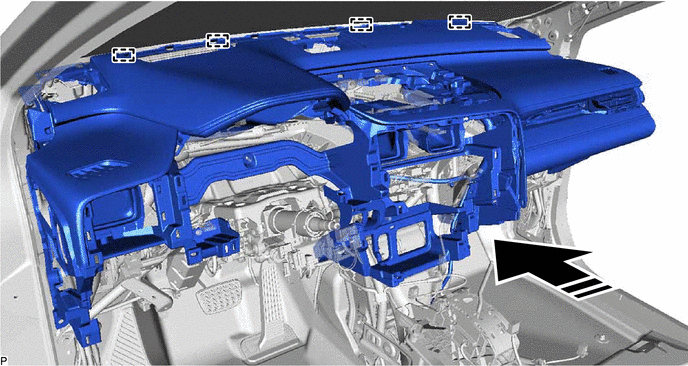
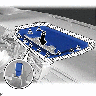
1. INSTALL INSTRUMENT PANEL SAFETY PAD SUB-ASSEMBLY
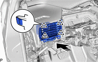
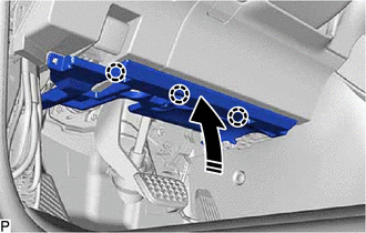
(a) Engage the 4 guides to temporarily install the instrument panel safety pad sub-assembly as shown in the illustration.
.png) | Install in this Direction | - | - |
NOTICE:
- Do not damage the instrument panel safety pad sub-assembly.
- Do not allow the wire harnesses to interfere with the surrounding parts.
(b) Install the instrument panel safety pad sub-assembly with the 7 bolts <C>, 2 bolts <A> and nut <G>.
.png)
| *a | Bolt <A> | *b | Bolt <C> |
| *c | Clip | *d | Nut <G> |
Torque:
Bolt<A> :
20 N·m {204 kgf·cm, 15 ft·lbf}
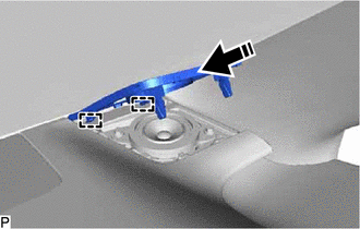
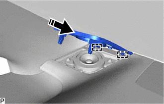
(c) Install the 2 clips.
(d) Engage each clamp.
.png)
| *A | w/ Telematics Transceiver | *B | w/ Rear No. 2 Seat |
(e) Connect each connector.
2. CONNECT NO. 2 INSTRUMENT PANEL WIRE
Click here .gif)
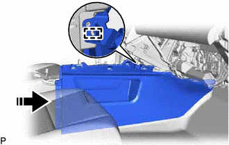
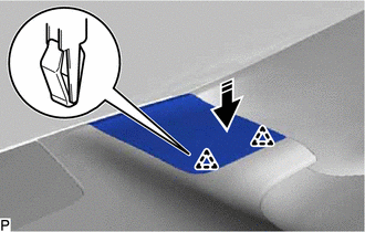
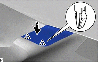
3. INSTALL FRONT NO. 2 CONSOLE BOX INSERT
(a) Engage the guide to install the front No. 2 console box insert as shown in the illustration.
| | Install in this Direction |
(b) Install the 4 screws <E>.
(c) Install the clip.
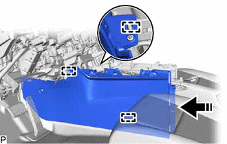
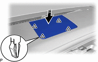
4. INSTALL FRONT NO. 1 CONSOLE BOX INSERT
(a) Engage the 3 guides to install the front No. 1 console box insert as shown in the illustration.
| | Install in this Direction |
(b) Install the 2 screws <E>.
(c) Install the clip.
5. INSTALL NO. 2 INSTRUMENT CLUSTER MOULDING
(a) w/ Interior Illumination:
(1) Connect the connector.
(b) Engage the 6 clips to install the No. 2 instrument cluster moulding as shown in the illustration.
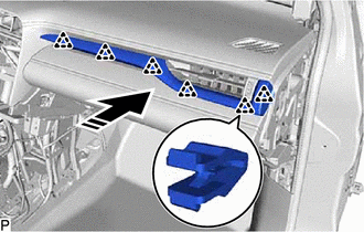
| | Install in this Direction |
6. INSTALL NO. 1 INSTRUMENT PANEL REGISTER ASSEMBLY
(a) Engage the 4 clips to install the No. 1 instrument panel register assembly as shown in the illustration.
| | Install in this Direction |
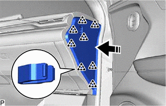
7. INSTALL FRONT PILLAR GARNISH RH
HINT:
Use the same procedure as for the LH side.
Click here
8. INSTALL FRONT NO. 2 SPEAKER ASSEMBLY (for RH Side)
HINT:
Use the same procedure as for the LH side.
Click here
9. INSTALL NO. 2 INSTRUMENT PANEL SPEAKER PANEL SUB-ASSEMBLY
(a) Engage the 2 guides as shown in the illustration.
| | Install in this Direction |
(b) Engage the 2 clips to install the No. 2 instrument panel speaker panel sub-assembly as shown in the illustration.
| | Install in this Direction |
10. INSTALL FRONT NO. 3 SPEAKER ASSEMBLY
Click here
11. INSTALL NO. 1 SPEAKER OPENING COVER ASSEMBLY
(a) Engage the 4 clips to install the No. 1 speaker opening cover assembly as shown in the illustration.
| | Install in this Direction |
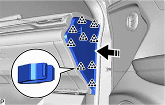
12. INSTALL FRONT PILLAR GARNISH LH
Click here
13. INSTALL FRONT NO. 2 SPEAKER ASSEMBLY (for LH Side)
Click here
14. INSTALL NO. 1 INSTRUMENT PANEL SPEAKER PANEL SUB-ASSEMBLY
(a) Engage the 2 guides as shown in the illustration.
| | Install in this Direction |
(b) Engage the 2 clips to install the No. 1 instrument panel speaker panel sub-assembly as shown in the illustration.
| | Install in this Direction |
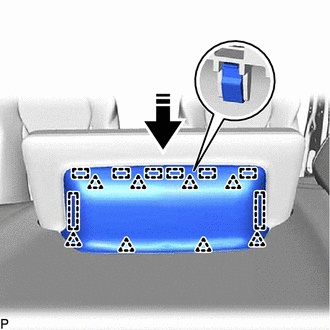
15. INSTALL GLOVE COMPARTMENT DOOR ASSEMBLY
(a) Engage the clamp.
(b) Connect the connector.
(c) Engage the 6 claws as shown in the illustration.
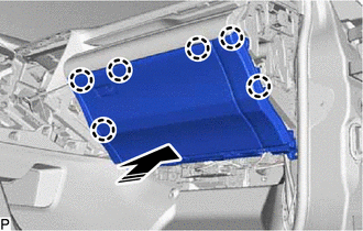
| | Install in this Direction |
(d) Install the 2 bolts <B> or <C>.
(e) Open the glove compartment door assembly.
(f) Install the glove compartment door assembly with the 3 screws <E>.
(g) Close the glove compartment door assembly.
16. INSTALL NO. 2 INSTRUMENT PANEL UNDER COVER SUB-ASSEMBLY
(a) Connect the connector.
(b) Engage the 2 guides as shown in the illustration.
| | Install in this Direction |
(c) Engage the 2 claws as shown in the illustration.
| | Install in this Direction |
(d) Install the No. 2 instrument panel under cover sub-assembly with the 2 screws <D>.
17. INSTALL COWL SIDE TRIM BOARD RH
HINT:
Use the same procedure as for the LH side.
Click here
18. INSTALL FRONT DOOR SCUFF PLATE RH
HINT:
Use the same procedure as for the LH side.
Click here
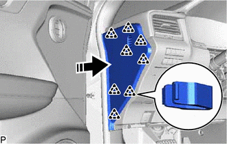
19. INSTALL INSTRUMENT PANEL GARNISH RH
(a) except TMMC Made:
(1) Engage the 8 clips to install the instrument panel garnish RH as shown in the illustration.
| | Install in this Direction |
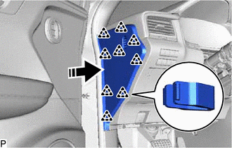
(b) for TMMC Made:
(1) Engage the 9 clips to install the instrument panel garnish RH as shown in the illustration.
| | Install in this Direction |
20. INSTALL CENTER INSTRUMENT CLUSTER FINISH PANEL SUB-ASSEMBLY
(a) Engage the 5 guides as shown in the illustration.
| | Install in this Direction (1) |
.png) | Install in this Direction (2) |
(b) Engage the 10 clips to install the center instrument cluster finish panel sub-assembly as shown in the illustration.
| | Install in this Direction |
21. INSTALL MULTI-DISPLAY ASSEMBLY
Click here
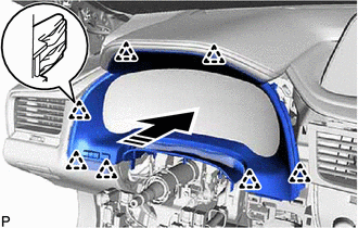
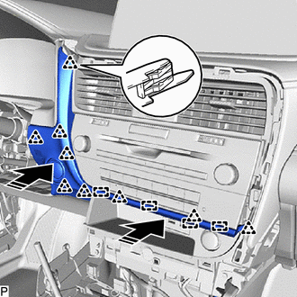
22. INSTALL INSTRUMENT PANEL FINISH PANEL SUB-ASSEMBLY
(a) Engage the 8 guides and 8 clips to install the instrument panel finish panel sub-assembly as shown in the illustration.
| | Install in this Direction |
23. INSTALL CONSOLE BOX ASSEMBLY
(a) Connect each connector.
(b) Engage the 5 clips to install the console box assembly as shown in the illustration.
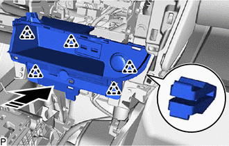
| | Install in this Direction |
24. INSTALL COOLER (ROOM TEMP. SENSOR) THERMISTOR
Click here
25. INSTALL RADIO RECEIVER ASSEMBLY WITH REGISTER
Click here
26. INSTALL COMBINATION METER ASSEMBLY
Click here
27. INSTALL INSTRUMENT CLUSTER FINISH PANEL SUB-ASSEMBLY
(a) Connect the connector.
(b) Engage the 7 clips to install the instrument cluster finish panel sub-assembly as shown in the illustration.
| | Install in this Direction |
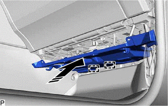
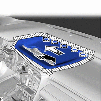
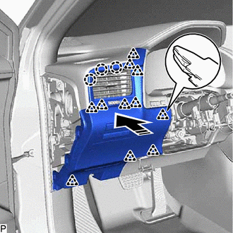
28. INSTALL LOWER NO. 1 INSTRUMENT PANEL AIRBAG ASSEMBLY
Click here
29. INSTALL LOWER INSTRUMENT FINISH PANEL SUB
(a) Connect the connector.
(b) Engage the 4 guides and 9 clips to install the lower instrument finish panel sub as shown in the illustration.
| | Install in this Direction |
30. INSTALL LOWER INSTRUMENT PANEL FINISH PANEL SUB-ASSEMBLY
(a) Connect each connector.
(b) Engage the 11 clips and 3 claws to install the lower instrument panel finish panel sub-assembly as shown in the illustration.
| | Install in this Direction |
(c) Install the 2 screws <D>.
| (d) Engage the 2 claws to connect the instrument panel hole cover. |
|
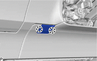
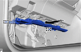
31. CONNECT HOOD LOCK CONTROL LEVER SUB-ASSEMBLY
(a) Engage the claw and 2 guides to connect the hood lock control lever sub-assembly.
32. INSTALL NO. 1 INSTRUMENT PANEL UNDER COVER SUB-ASSEMBLY
(a) Engage the 2 claws to connect the DLC3 connector.
(b) Engage the clamp.
(c) Connect the connector.
(d) Engage the 2 guides as shown in the illustration.
| | Install in this Direction |
(e) Engage the 3 claws as shown in the illustration.
| | Install in this Direction |
(f) Install the No. 1 instrument panel under cover sub-assembly with the 2 screws <D>.
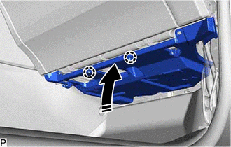
33. INSTALL COWL SIDE TRIM BOARD LH
Click here
34. INSTALL FRONT DOOR SCUFF PLATE LH
Click here
35. INSTALL INSTRUMENT PANEL GARNISH LH
(a) except TMMC Made:
(1) Engage the 8 clips to install the instrument panel garnish LH as shown in the illustration.
| | Install in this Direction |
(b) for TMMC Made:
(1) Engage the 9 clips to install the instrument panel garnish RH as shown in the illustration.
| | Install in this Direction |
36. INSTALL CONSOLE BOX ASSEMBLY
Click here
37. INSTALL HEADLIGHT DIMMER SWITCH ASSEMBLY
Click here
 Removal
REMOVAL CAUTION / NOTICE / HINT The necessary procedures (adjustment, calibration, initialization or registration) that must be performed after parts are removed and installed, or replaced during inst ...

Other materials:
Lexus RX (RX 350L, RX450h) 2016-2026 Repair Manual > Intuitive Parking Assist System (w/ Intelligent Clearance Sonar System): No. 2 Clearance Warning Buzzer Circuit
DESCRIPTION This circuit consists of the No. 2 clearance warning buzzer and clearance warning ECU assembly. An ECU-excited type buzzer is used. The ECU operates the buzzers using a sound pattern that changes depending on the distance to the obstacle. WIRING DIAGRAM PROCEDURE 1. PERFORM ACTIVE ...
Lexus RX (RX 350L, RX450h) 2016-2026 Repair Manual > Power Outlet Socket: Installation
INSTALLATION PROCEDURE 1. INSTALL NO. 2 USB CHARGER SOCKET (a) Engage the 4 claws to install the No. 2 USB charger socket as shown in the illustration. Install in this Direction 2. INSTALL POWER OUTLET SOCKET LENS (a) Engage the 2 claws to install the power outlet socket lens as shown in t ...
Lexus RX (RX 350L, RX450h) 2016-{YEAR} Owners Manual
- For your information
- Pictorial index
- For safety and security
- Instrument cluster
- Operation of each component
- Driving
- Lexus Display Audio system
- Interior features
- Maintenance and care
- When trouble arises
- Vehicle specifications
- For owners
Lexus RX (RX 350L, RX450h) 2016-{YEAR} Repair Manual

0.0103