Lexus RX (RX 350L, RX450h) 2016-2026 Repair Manual: No. 2 Clearance Warning Buzzer Circuit
DESCRIPTION
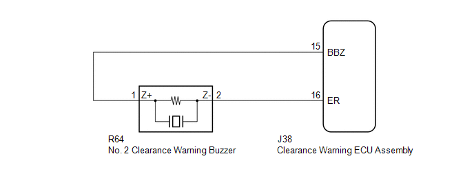
This circuit consists of the No. 2 clearance warning buzzer and clearance warning ECU assembly. An ECU-excited type buzzer is used. The ECU operates the buzzers using a sound pattern that changes depending on the distance to the obstacle.
WIRING DIAGRAM
PROCEDURE
| 1. | PERFORM ACTIVE TEST USING GTS (REAR BUZZER) |
(a) Connect the Techstream to the DLC3.
(b) Turn the engine switch on (IG).
(c) Turn the Techstream on.
(d) Enter the following menus: Body Electrical / Advanced Parking Guidance/ICS/Intuitive P/A / Active Test.
(e) Check that the rear buzzer operates by performing the Active Test.
Body Electrical > Advanced Parking Guidance/ICS/Intuitive P/A > Active Test| Tester Display | Measurement Item | Control Range | Diagnostic Note |
|---|---|---|---|
| Rear Buzzer | No. 2 clearance warning buzzer | Stop or Operate | Confirm that the vehicle is stopped and the engine switch is on (IG) |
| Tester Display |
|---|
| Rear Buzzer |
OK:
The No. 2 clearance warning buzzer sounds.
| OK |  | PROCEED TO NEXT SUSPECTED AREA SHOWN IN PROBLEM SYMPTOMS TABLE |
|

| 2. | CHECK HARNESS AND CONNECTOR (CLEARANCE WARNING ECU ASSEMBLY - NO. 2 CLEARANCE WARNING BUZZER) |
(a) Disconnect the J38 clearance warning ECU assembly connector.
(b) Disconnect the R64 No. 2 clearance warning buzzer connector.
(c) Measure the resistance according to the value(s) in the table below.
Standard Resistance:
| Tester Connection | Condition | Specified Condition |
|---|---|---|
| J38-15 (BBZ) - R64-1 (Z+) | Always | Below 1 Ω |
| J38-16 (ER) - R64-2 (Z-) | Always | Below 1 Ω |
| J38-15 (BBZ) or R64-1 (Z+) - Body ground | Always | 10 kΩ or higher |
| J38-16 (ER) or R64-2 (Z-) - Body ground | Always | 10 kΩ or higher |
| NG | | REPAIR OR REPLACE HARNESS OR CONNECTOR |
|
| 3. | REPLACE NO. 2 CLEARANCE WARNING BUZZER |
(a) Replace the No. 2 clearance warning buzzer with a new or known good one.
w/o Rear No. 2 Seat: Click here .gif)
w/ Rear No. 2 Seat: Click here
|
| 4. | PERFORM ACTIVE TEST USING TECHSTREAM (REAR BUZZER) |
(a) Connect the Techstream to the DLC3.
(b) Turn the engine switch on (IG).
(c) Turn the Techstream on.
(d) Enter the following menus: Body Electrical / Advanced Parking Guidance/ICS/Intuitive P/A / Active Test.
(e) Check that the rear buzzer operates by performing the Active Test.
Body Electrical > Advanced Parking Guidance/ICS/Intuitive P/A > Active Test| Tester Display | Measurement Item | Control Range | Diagnostic Note |
|---|---|---|---|
| Rear Buzzer | No. 2 clearance warning buzzer | Stop or Operate | Confirm that the vehicle is stopped and the engine switch is on (IG) |
| Tester Display |
|---|
| Rear Buzzer |
OK:
The No. 2 clearance warning buzzer sounds.
| OK | | END |
| NG | | REPLACE CLEARANCE WARNING ECU ASSEMBLY |
 Clearance Warning ECU Power Source Circuit
DESCRIPTION This circuit provides power to operate the clearance warning ECU assembly. WIRING DIAGRAM CAUTION / NOTICE / HINT NOTICE: Inspect the fuses for circuits related to this system before perf ...
 Sensor Frozen Indication (Dirty or Frozen)
DESCRIPTION When the ultrasonic sensor is dirty or frozen, "Parking Assist Unavailable Clean Parking Assist Sensor" is displayed on the multi-information display in the combination meter assembly. PRO ...
Other materials:
Lexus RX (RX 350L, RX450h) 2016-2026 Repair Manual > Power Mirror Control System (w/ Memory): Customize Parameters
CUSTOMIZE PARAMETERS CUSTOMIZE POWER MIRROR CONTROL SYSTEM (w/ Memory) HINT: The following items can be customized. NOTICE:
When the customer requests a change in a function, first make sure that the function can be customized.
Record the current settings before customizing.
(a) Customizing ...
Lexus RX (RX 350L, RX450h) 2016-2026 Repair Manual > Climate Control Seat System: Parts Location
PARTS LOCATION ILLUSTRATION *1 ENGINE ROOM RELAY BLOCK AND JUNCTION BLOCK ASSEMBLY - ECU-IG1 NO. 9 FUSE - - ILLUSTRATION *1 REFRESHING SEAT SWITCH (for Front Side) *2 COMBINATION METER ASSEMBLY *3 AIR CONDITIONING AMPLIFIER ASSEMBLY *4 INSTRUMENT PANEL JUNCTION BLOCK ...
Lexus RX (RX 350L, RX450h) 2016-{YEAR} Owners Manual
- For your information
- Pictorial index
- For safety and security
- Instrument cluster
- Operation of each component
- Driving
- Lexus Display Audio system
- Interior features
- Maintenance and care
- When trouble arises
- Vehicle specifications
- For owners
Lexus RX (RX 350L, RX450h) 2016-{YEAR} Repair Manual

0.0111