Lexus RX (RX 350L, RX450h) 2016-2026 Repair Manual: Removal
REMOVAL
CAUTION / NOTICE / HINT
The necessary procedures (adjustment, calibration, initialization or registration) that must be performed after parts are removed and installed, or replaced during roof headlining removal/installation are shown below.
Necessary Procedures After Parts Removed/Installed/Replaced| Replaced Part or Performed Procedure | Necessary Procedure | Effect/Inoperative Function when Necessary Procedure not Performed | Link |
|---|---|---|---|
| Disconnect cable from negative battery terminal | Memorize steering angle neutral point | Lane Control System | |
| Pre-collision System | |||
| Intelligent Clearance Sonar System*1 | |||
| Lighting System (w/ Automatic Headlight Beam Level Control System) | | ||
| Parking Assist Monitor System | | ||
| Panoramic View Monitor System | | ||
| Initialize back door lock | Power Door Lock Control System | | |
| Reset back door close position | Power Back Door System (w/ Outside Door Control Switch) | |
*1: When performing learning using the Techstream.
Click here .gif)
CAUTION:
Some of these service operations affect the SRS airbag system. Read the precautionary notices concerning the SRS airbag system before servicing.
.png)
Click here
PROCEDURE
1. REMOVE TONNEAU COVER ASSEMBLY
(a) Remove the tonneau cover assembly.
2. REMOVE DECK BOARD ASSEMBLY
(a) Remove the deck board assembly.
3. REMOVE REAR NO. 3 FLOOR BOARD
(a) Remove the rear No. 3 floor board.
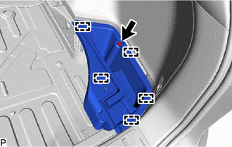
4. REMOVE REAR DECK FLOOR BOX
| (a) Remove the 3 clips. |
|
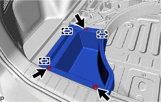
(b) Disengage the 3 guides to remove the rear deck floor box.
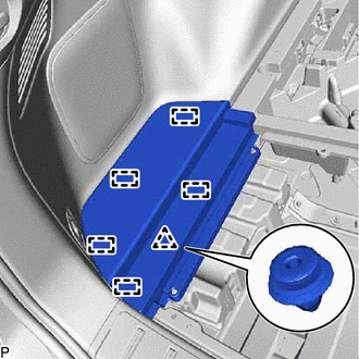
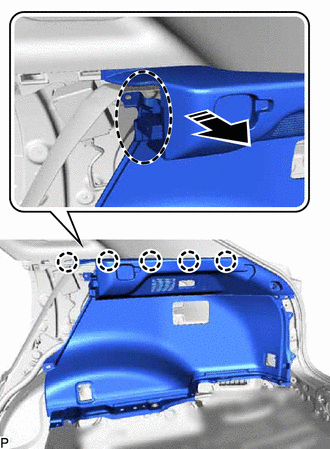
5. REMOVE REAR NO. 4 FLOOR BOARD
| (a) Disengage the clip and 5 guides to remove the rear No. 4 floor board. |
|
6. REMOVE FRONT DECK FLOOR BOX
| (a) Remove the clip. |
|
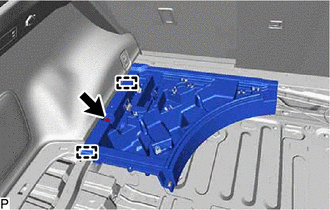
(b) Disengage the 2 guides to remove the front deck floor box.
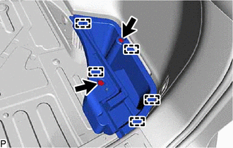
7. REMOVE DECK SIDE TRIM BOX RH
| (a) for TMC Made: (1) Using a clip remover, remove the 2 clips. (2) Disengage the 5 guides to remove the deck side trim box RH. |
|
| (b) for TMMC Made: (1) Using a clip remover, remove the clip. (2) Disengage the 5 guides to remove the deck side trim box RH. |
|
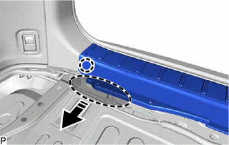
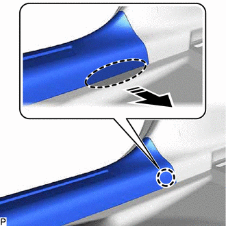
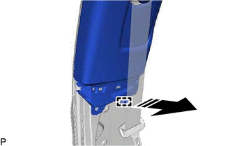
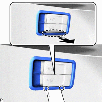
8. REMOVE REAR FLOOR FINISH PLATE
(a) Disengage the claw as shown in the illustration.
.png) | Place Hand Here |
.png) | Remove in this Direction |
HINT:
Use the same procedure for the RH side and LH side.
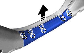
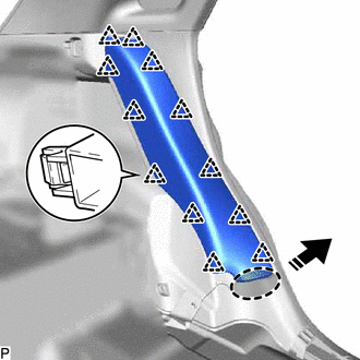
(b) Disengage the 2 claws, 4 clips and 2 guides to remove the rear floor finish plate as shown in the illustration.
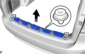
| | Remove in this Direction |
9. REMOVE FRONT DOOR SCUFF PLATE LH
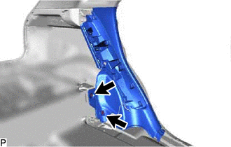
(a) Disengage the claw as shown in the illustration.
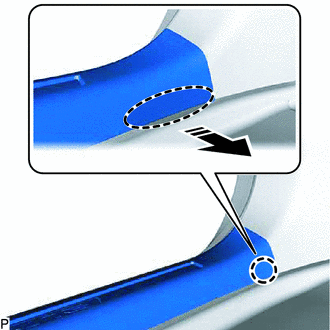
| | Place Hand Here |
| | Remove in this Direction |
HINT:
Use the same procedure for the front side and rear side.
(b) Disengage the 8 claws and 2 guides to remove the front door scuff plate LH as shown in the illustration.
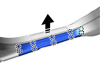
| | Remove in this Direction |
(c) w/ Illumination:
(1) Disconnect the connector.
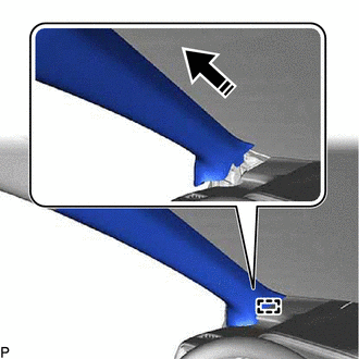
10. REMOVE FRONT PILLAR GARNISH LH
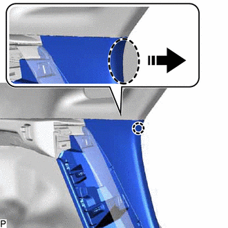
(a) Apply protective tape around the front pillar garnish LH as shown in the illustration.
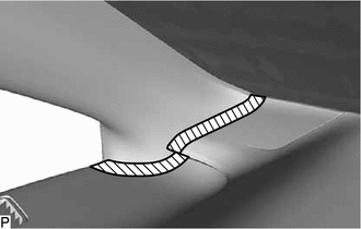
.png) | Protective Tape |
(b) Pull the upper part of the front pillar garnish LH toward the inside of the cabin to disengage the clip and the front pillar garnish LH from the base of the front pillar garnish clip.
HINT:
Let the front pillar garnish LH hang from the front pillar garnish clip.
| *1 | Front Pillar Garnish Clip |
| | Place Hand Here |
| | Remove in this Direction |
| (c) Cut off the front pillar garnish clip as shown in the illustration. NOTICE: Replace the front pillar garnish clip with a new one. |
|
(d) Using a clip remover, remove the front pillar garnish clip from the vehicle body.
(e) Disengage the guide to remove the front pillar garnish LH as shown in the illustration.
| | Remove in this Direction |
(f) Remove the clip from the front pillar garnish LH.
| (g) Protect the curtain shield airbag assembly LH. (1) Cover the curtain shield airbag assembly LH with a piece of cloth or nylon and secure the edges of the cover with tape as shown in the illustration. NOTICE: Cover the curtain shield airbag assembly LH with a protective cover as soon as the front pillar garnish LH is removed. |
|
11. REMOVE REAR DOOR SCUFF PLATE LH
(a) Disengage the claw as shown in the illustration.
| | Place Hand Here |
| | Remove in this Direction |
HINT:
Use the same procedure for the front side and rear side.
(b) Disengage the 8 claws and 2 guides to remove the rear door scuff plate LH as shown in the illustration.
| | Remove in this Direction |
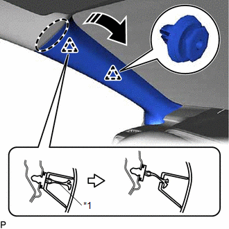
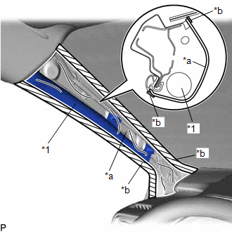
12. REMOVE LOWER CENTER PILLAR GARNISH LH
(a) Pull the lower center pillar garnish LH in the directions indicated by the arrows (1) shown in the illustration to disengage the 2 claws (A).
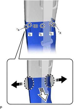
| *a | Claw (A) |
| *b | Claw (B) |
| | Place Hand Here |
| | Remove in this Direction (1) |
.png) | Remove in this Direction (2) |
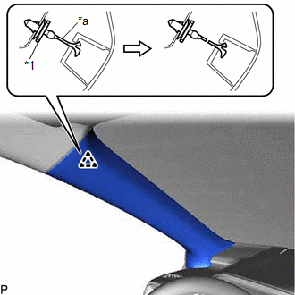
(b) Pull the lower center pillar garnish LH in the direction indicated by the arrow (2) shown in the illustration to disengage the guide and 3 claws (B).
(c) Disengage the 5 clips to remove the lower center pillar garnish LH as shown in the illustration.
| | Place Hand Here |
| | Remove in this Direction |
13. DISCONNECT FRONT SEAT OUTER BELT ASSEMBLY LH
Click here
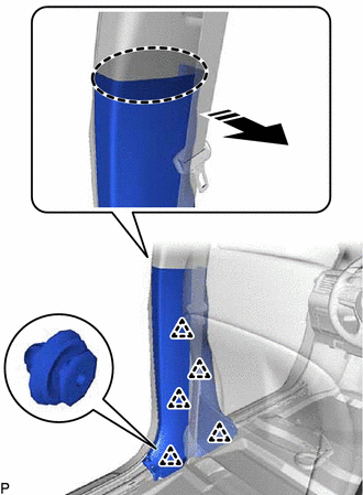
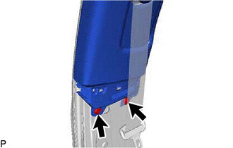
14. REMOVE CENTER PILLAR GARNISH ASSEMBLY LH
| (a) Using a clip remover, remove the 2 clips. |
|
(b) Disengage the clip as shown in the illustration.
| | Place Hand Here |
| | Remove in this Direction |
(c) Disengage the guide to remove the center pillar garnish assembly LH as shown in the illustration.
| | Remove in this Direction |
(d) Remove the clip from the center pillar garnish assembly LH.
15. REMOVE FRONT DOOR SCUFF PLATE RH
HINT:
Use the same procedure as for the LH side.
16. REMOVE FRONT PILLAR GARNISH RH
HINT:
Use the same procedure as for the LH side.
17. REMOVE REAR DOOR SCUFF PLATE RH
HINT:
Use the same procedure as for the LH side.
18. REMOVE LOWER CENTER PILLAR GARNISH RH
HINT:
Use the same procedure as for the LH side.
19. DISCONNECT FRONT SEAT OUTER BELT ASSEMBLY RH
HINT:
Use the same procedure as for the LH side.
20. REMOVE CENTER PILLAR GARNISH ASSEMBLY RH
HINT:
Use the same procedure as for the LH side.
21. REMOVE REAR SEAT ASSEMBLY LH
Click here
22. REMOVE REAR SEAT ASSEMBLY RH
Click here
23. REMOVE UPPER QUARTER TRIM PAD LH
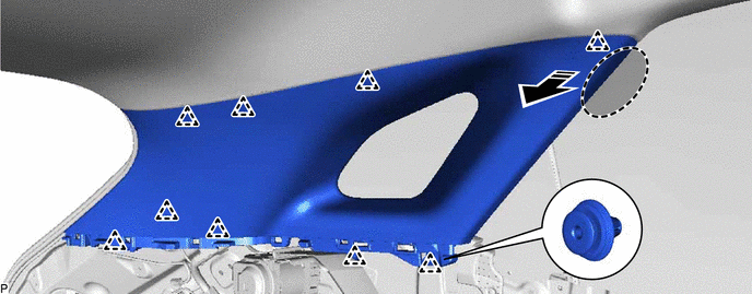
(a) Disengage the 12 clips to remove the upper quarter trim pad LH as shown in the illustration.
| | Place Hand Here |
| | Remove in this Direction |
24. REMOVE REAR SEAT SIDE GARNISH LH
| (a) Using a clip remover, remove the 2 clips. |
|
(b) Disengage the claw as shown in the illustration.
| | Place Hand Here |
| | Remove in this Direction |
(c) Disengage the 4 claws and 4 clips to remove the rear seat side garnish LH as shown in the illustration.
| | Remove in this Direction |
25. REMOVE REAR FLOOR FINISH SIDE PLATE LH
(a) Disengage the 2 claws, 2 clips and guide to remove the rear floor finish side plate LH.
| | Place Hand Here |
| | Remove in this Direction |
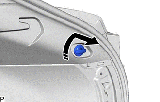
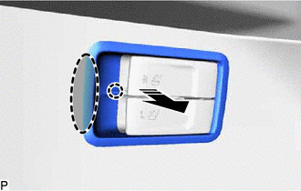
26. REMOVE NO. 1 LUGGAGE COMPARTMENT TRIM HOOK (for LH Side)
(a) Turn the No. 1 luggage compartment trim hook as shown in the illustration to remove it.
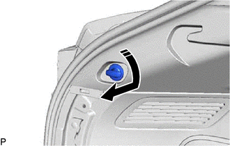
| | Remove in this Direction |
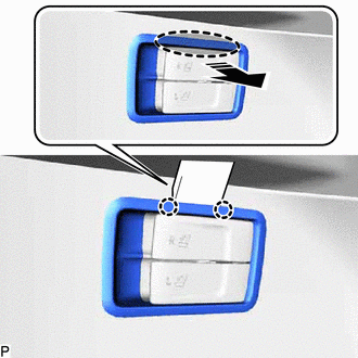
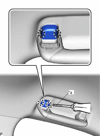
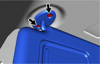
27. REMOVE ROPE HOOK ASSEMBLY (for LH Side)
| (a) Using a screwdriver with its tip wrapped with protective tape, disengage the 4 claws and open each cover. |
|
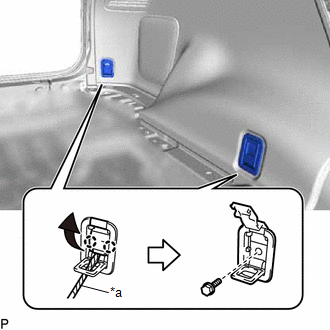
(b) Remove the 2 bolts and 2 rope hook assemblies.
28. REMOVE NO. 1 LUGGAGE COMPARTMENT LIGHT ASSEMBLY (for LH Side)
Click here
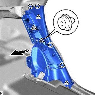
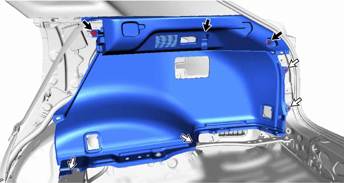
29. REMOVE DECK TRIM SIDE PANEL ASSEMBLY LH
(a) Remove the 3 bolts.
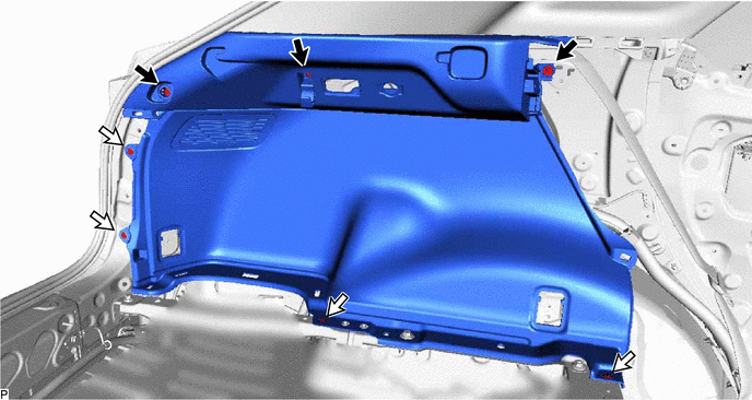
.png) | Bolt | .png) | Clip |
(b) Using a clip remover, remove the 4 clips.
(c) Disengage the 5 claws as shown in the illustration.
| | Place Hand Here |
| | Remove in this Direction |
(d) Disconnect the connector to remove the deck trim side panel assembly LH.
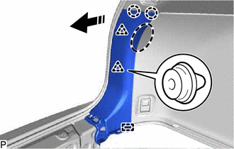
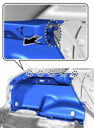
30. REMOVE ROOF SIDE INNER GARNISH ASSEMBLY LH
(a) Disengage the 9 clips to remove the roof side inner garnish assembly LH.
| | Place Hand Here | | Remove in this Direction |
(b) Remove the 9 clips from the roof side inner garnish assembly LH.
31. REMOVE UPPER QUARTER TRIM PAD RH
HINT:
Use the same procedure as for the LH side.
32. REMOVE REAR SEAT SIDE GARNISH RH
HINT:
Use the same procedure as for the LH side.
33. REMOVE REAR FLOOR FINISH SIDE PLATE RH
HINT:
Use the same procedure as for the LH side.
34. REMOVE NO. 1 LUGGAGE COMPARTMENT TRIM HOOK (for RH Side)
(a) Turn the No. 1 luggage compartment trim hook as shown in the illustration to remove it.
| | Remove in this Direction |
35. REMOVE ROPE HOOK ASSEMBLY (for RH Side)
HINT:
Use the same procedure as for the LH side.
36. REMOVE NO. 1 LUGGAGE COMPARTMENT LIGHT ASSEMBLY (for RH Side)
Click here
37. REMOVE RECLINING REMOTE CONTROL BEZEL RH (w/o Rear Power Seat System)
(a) Using a moulding remover, disengage the 2 claws as shown in the illustration.
| | Insert Moulding Remover Here |
| | Remove in this Direction |
(b) Using a moulding remover, disengage the 2 claws as shown in the illustration.
| | Insert Moulding Remover Here |
| | Remove in this Direction |
(c) Disengage the claw to remove the reclining remote control bezel RH.
| | Place Hand Here |
| | Remove in this Direction |
38. REMOVE FOLD SEAT SWITCH ASSEMBLY (w/ Rear Power Seat System)
Click here
39. REMOVE DECK TRIM SIDE PANEL ASSEMBLY RH
(a) Remove the 3 bolts.
| | Bolt | | Clip |
(b) Using a clip remover, remove the 4 clips.
(c) Disengage the 5 claws to remove the deck trim side panel assembly RH as shown in the illustration.
| | Place Hand Here |
| | Remove in this Direction |
40. REMOVE ROOF SIDE INNER GARNISH ASSEMBLY RH
HINT:
Use the same procedure as for the LH side.
41. REMOVE MAP LIGHT ASSEMBLY
Click here
42. REMOVE SPOT LIGHT ASSEMBLY
Click here
43. REMOVE RAIN SENSOR COVER (w/ Rain Sensor)
Click here
44. REMOVE RAIN SENSOR (w/ Rain Sensor)
Click here
45. REMOVE NO. 2 FORWARD RECOGNITION COVER
Click here
46. REMOVE NO. 1 FORWARD RECOGNITION COVER
Click here
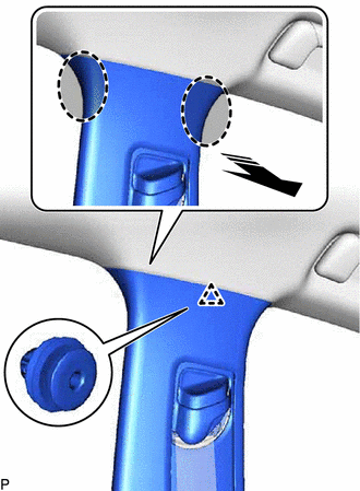
47. REMOVE ASSIST GRIP ASSEMBLY
HINT:
Use the same procedure for all assist grip assemblies.
(a) Using a screwdriver with its tip wrapped with protective tape, disengage the 2 claws and remove the assist grip cover LH.
| *a | Protective Tape |
| | Insert Screwdriver Here |
HINT:
Use the same procedure for the RH side and LH side.
(b) Disengage the 2 clips to remove the assist grip assembly.
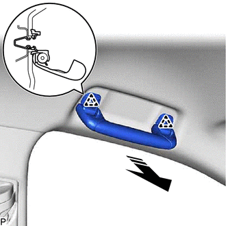
| | Remove in this Direction |
(c) Remove the 2 clips from the vehicle body.
48. REMOVE REAR ASSIST GRIP ASSEMBLY LH
HINT:
Use the same procedure as for the assist grip assembly.
49. REMOVE REAR ASSIST GRIP ASSEMBLY RH
HINT:
Use the same procedure as for the assist grip assembly.
50. REMOVE VISOR BRACKET COVER (for LH Side)
(a) Using a moulding remover, disengage the 4 claws and remove the visor bracket cover as shown in the illustration.
| | Insert Moulding Remover Here |
51. REMOVE VISOR ASSEMBLY LH
| (a) Remove the 2 screws. |
|
(b) Pull the visor assembly LH in the direction indicated by the arrow (1) shown in the illustration to disconnect it from the visor holder.
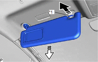
| *1 | Visor Holder |
| | Remove in this Direction (1) |
| | Remove in this Direction (2) |
(c) Pull the visor assembly LH in the direction indicated by the arrow (2) shown in the illustration to remove it.
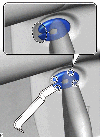
52. REMOVE VISOR HOLDER (for LH Side)
(a) Turn the visor holder approximately 45° and pull it out as indicated by the arrows, in the order shown in the illustration.
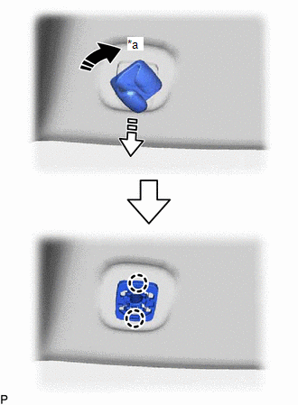
| *a | 45° |
| | Remove in this Direction (1) |
| | Remove in this Direction (2) |
(b) Disengage the 2 claws to remove the visor holder.
53. REMOVE VISOR BRACKET COVER (for RH Side)
HINT:
Use the same procedure as for the LH side.
54. REMOVE VISOR ASSEMBLY RH
HINT:
Use the same procedure as for the LH side.
55. REMOVE VISOR HOLDER (for RH Side)
HINT:
Use the same procedure as for the LH side.
56. REMOVE ROOF HEADLINING ASSEMBLY
(a) for Windshield Glass Side:
(1) Disconnect each connector.
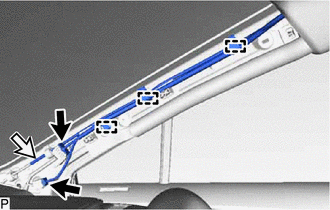
(b) for Front Pillar LH Side:
(1) Remove the protective cover.
| (2) Disengage the 4 clamps. |
|
.png)
(3) Disconnect the 3 connectors.
(4) Install the protective cover.
(c) for Front Pillar RH Side:
(1) Remove the protective cover.
(2) Disengage the 3 clamps.
(3) Disconnect each connector and the washer hose assembly.
| | Connector |
| | Washer Hose Assembly |
HINT:
Use a container to collect the windshield washer fluid.
(4) Install the protective cover.
(d) for Rear Pillar RH Side:
(1) Disengage each clamp.
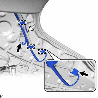
| | Connector |
| | Washer Hose Assembly |
(2) Disconnect each connector and the washer hose assembly.
HINT:
Use a container to collect the windshield washer fluid.
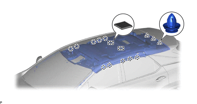
(e) for Standard Roof:
(1) Disengage the 10 claws, 3 clips and 2 fasteners.
(f) for Sliding Roof:
(1) Disconnect the connector.
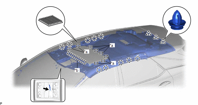
| *a | Fastener | *b | Guide |
(2) Disengage the 10 claws, 3 clips, 8 fasteners and guide.
(g) for Panoramic Moon Roof:
(1) Disconnect the 2 connectors.
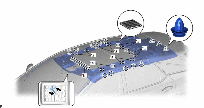
| *a | Fastener | *b | Guide |
(2) Disengage the 10 claws, 3 clips, 13 fasteners and guide.
(h) Remove the roof headlining assembly from the vehicle through the back door as shown in the illustration.
NOTICE:
Do not damage the roof headlining assembly or vehicle interior.
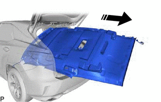
| | Remove in this Direction |
 Reassembly
REASSEMBLY PROCEDURE 1. INSTALL NO. 2 ROOF SILENCER PAD (for TMC Made) (a) Remove the release paper from 2 new No. 2 roof silencer pads. HINT: After removing the release paper, keep the exposed adhesi ...
 Lighting (int)
...
Other materials:
Lexus RX (RX 350L, RX450h) 2016-2026 Repair Manual > Differential Case: Inspection
INSPECTION PROCEDURE 1. INSPECT DIFFERENTIAL CASE ASSEMBLY (a) Using SST, rotate the front differential side gear as shown in the illustration. SST: 09528-52010 09528-05030 Standard: The front differential side gear does not lock when rotated in either direction. If the result is not as specifie ...
Lexus RX (RX 350L, RX450h) 2016-2026 Repair Manual > Navigation System: Voice Guidance does not Function
WIRING DIAGRAM PROCEDURE 1. CHECK VOICE GUIDANCE SETTING (a) Check that the voice guidance settings are not off. OK: Voice guidance settings are not off. NG CHANGE VOICE GUIDANCE SETTINGS TO ON
OK 2. CHECK HARNESS AND CONNECTOR (RADIO RECEIVER ASSEMBLY - NA ...
Lexus RX (RX 350L, RX450h) 2016-{YEAR} Owners Manual
- For your information
- Pictorial index
- For safety and security
- Instrument cluster
- Operation of each component
- Driving
- Lexus Display Audio system
- Interior features
- Maintenance and care
- When trouble arises
- Vehicle specifications
- For owners
Lexus RX (RX 350L, RX450h) 2016-{YEAR} Repair Manual

0.0099