Lexus RX (RX 350L, RX450h) 2016-2026 Repair Manual: IG Signal Circuit
DESCRIPTION
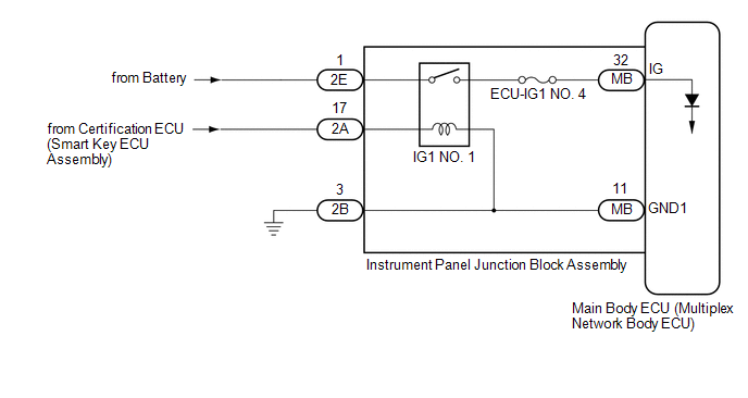
This circuit detects the engine switch on (IG) or off condition, and sends it to the main body ECU (multiplex network body ECU).
WIRING DIAGRAM
CAUTION / NOTICE / HINT
NOTICE:
- Inspect the fuses for circuits related to this system before performing the following procedure.
-
Before replacing the main body ECU (multiplex network body ECU), refer to Registration.
Click here
.gif)
PROCEDURE
| 1. | CHECK FOR DTC (SMART ACCESS SYSTEM WITH PUSH-BUTTON START (for Start Function)) |
(a) Clear the DTCs.
Click here
(b) Check for DTCs.
Click here
| Result | Proceed to |
|---|---|
| Smart Access System with Push-button Start (for Start Function) DTCs are not output | A |
| Smart Access System with Push-button Start (for Start Function) DTCs are output | B |
| B | .gif) | GO TO SMART ACCESS SYSTEM WITH PUSH-BUTTON START (for Start Function) |
|
.gif)
| 2. | READ VALUE USING TECHSTREAM |
(a) Connect the Techstream to the DLC3.
(b) Turn the engine switch on (IG).
(c) Turn the Techstream on.
(d) Enter the following menus: Body Electrical / Main Body / Data List.
(e) Read the Data List according to the display on the Techstream.
Body Electrical > Main Body > Data List| Tester Display | Measurement Item | Range | Normal Condition | Diagnostic Note |
|---|---|---|---|---|
| IG SW | Engine switch on (IG) signal | ON or OFF | ON: Engine switch on (IG) OFF: Engine switch off | - |
| Tester Display |
|---|
| IG SW |
OK:
Normal conditions listed above are displayed.
| OK | | PROCEED TO NEXT SUSPECTED AREA SHOWN IN PROBLEM SYMPTOMS TABLE |
|
| 3. | CHECK HARNESS AND CONNECTOR (POWER SOURCE - INSTRUMENT PANEL JUNCTION BLOCK ASSEMBLY) |
(a) Disconnect the 2E instrument panel junction block assembly connector.
(b) Measure the voltage according to the value(s) in the table below.
Standard Voltage:
| Tester Connection | Condition | Specified Condition |
|---|---|---|
| 2E-1 - Body ground | Always | 11 to 14 V |
| NG | | REPAIR OR REPLACE HARNESS OR CONNECTOR |
|
| 4. | INSPECT INSTRUMENT PANEL JUNCTION BLOCK ASSEMBLY |
(a) Remove the instrument panel junction block assembly.
Click here
(b) Remove the main body ECU (multiplex network body ECU) from the instrument panel junction block assembly.
Click here
(c) Measure the resistance according to the value(s) in the table below.
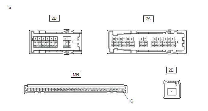
| *a | Component without harness connected (Instrument Panel Junction Block Assembly) | - | - |
Standard Resistance:
| Tester Connection | Condition | Specified Condition |
|---|---|---|
| 2E-1 - MB-32 (IG) | Battery not connected to 2A-17 and 2B-3 | 10 kΩ or higher |
| 2E-1 - MB-32 (IG) | Battery positive (+) → 2A-17 Battery negative (-) → 2B-3 | Below 1 Ω |
| OK | | REPLACE MAIN BODY ECU (MULTIPLEX NETWORK BODY ECU) |
| NG | | REPLACE INSTRUMENT PANEL JUNCTION BLOCK ASSEMBLY |
 Data List / Active Test
DATA LIST / ACTIVE TEST DATA LIST NOTICE: In the following table, the values listed under "Normal Condition" are reference values. Do not depend solely on these reference values when deciding whether ...
 ACC Signal Circuit
DESCRIPTION This circuit detects the engine switch on (ACC) or off condition, and sends it to the main body ECU (multiplex network body ECU). WIRING DIAGRAM CAUTION / NOTICE / HINT NOTICE:
Inspect ...
Other materials:
Lexus RX (RX 350L, RX450h) 2016-2026 Repair Manual > Mass Air Flow Meter: Removal
REMOVAL CAUTION / NOTICE / HINT The necessary procedures (adjustment, calibration, initialization or registration) that must be performed after parts are removed and installed, or replaced during mass air flow meter sub-assembly removal/installation are shown below. Necessary Procedures After Parts ...
Lexus RX (RX 350L, RX450h) 2016-2026 Repair Manual > Front Seat Side Airbag Assembly: Installation
INSTALLATION CAUTION / NOTICE / HINT HINT:
Use the same procedure for the RH side and LH side.
The following procedure is for the LH side.
PROCEDURE 1. INSTALL FRONT SEAT AIRBAG ASSEMBLY (a) Install the front seat airbag assembly with 2 new nuts. Torque: 5.5 N·m {56 kgf·cm, 49 in·lbf} N ...
Lexus RX (RX 350L, RX450h) 2016-{YEAR} Owners Manual
- For your information
- Pictorial index
- For safety and security
- Instrument cluster
- Operation of each component
- Driving
- Lexus Display Audio system
- Interior features
- Maintenance and care
- When trouble arises
- Vehicle specifications
- For owners
Lexus RX (RX 350L, RX450h) 2016-{YEAR} Repair Manual

0.0154