Lexus RX (RX 350L, RX450h) 2016-2026 Repair Manual: ABS Pump Motor Control Circuit Open (C052C13,C052C49,C052F14)
DESCRIPTION
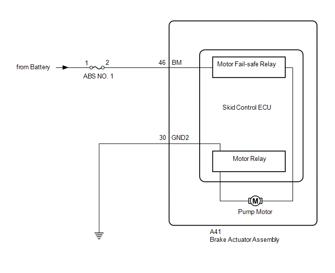
The motor relay and motor fail safe relay are built into the brake actuator assembly.
When the skid control ECU (brake actuator assembly) operate ABS, TRAC, VSC, brake hold or brake assist, the motor relay turns ON and drives the motor pump built into the brake actuator assembly.
If any DTCs related to motor supply power are stored, fail-safe is performed and supply of power to the motor relay is cut by the motor fail safe relay.
If the voltage supplied to the motor relay (BM) is below the DTC detection threshold due to low voltage from the battery or alternator, these DTCs may be stored.
| DTC No. | Detection Item | DTC Detection Condition | Trouble Area |
|---|---|---|---|
| C052C13 | ABS Pump Motor Control Circuit Open | Either of the following is detected:
|
|
| C052C49 | ABS Pump Motor Control Internal Electronic Failure | Any of the following is detected:
|
|
| C052F14 | ABS Pump Motor Supply Voltage Circuit Short to Ground or Open | When voltage at +BS terminal is 9.5 V or higher, open in BM terminal continues for 1 second or more. |
|
| Vehicle Condition | |||
|---|---|---|---|
| Pattern 1 | Pattern 2 | ||
| Diagnosis Condition | When the +BS terminal voltage is from 9.5 to 17.4 V | ○ | ○ |
| Malfunction Status | Motor relay ON while control operates, relay contact OFF condition continues | ○ | - |
| Motor relay supervision voltage malfunction continues, motor relay turns ON during control operation | - | ○ | |
| Detection Time | 0.12 seconds or more | 0.12 seconds or more | |
| Number of Trips | 1 trip | 1 trip | |
HINT:
DTC will be output when conditions for either of the patterns in the table above are met.
DTC Detection Conditions: C052C49| Vehicle Condition | ||||
|---|---|---|---|---|
| Pattern 1 | Pattern 2 | Pattern 3 | ||
| Diagnosis Condition | When the +BS terminal voltage is from 9.5 to 17.4 V | ○ | ○ | - |
| Malfunction Status | Overcurrent in motor relay and motor fail-safe relay continues | ○ | - | - |
| Motor relay overcurrent continues | - | ○ | - | |
| Motor relay gate voltage malfunction continues | - | - | ○ | |
| Detection Time | 0.05 seconds or more | 0.05 seconds or more | 0.12 seconds or more | |
| Number of Trips | 1 trip | 1 trip | 1 trip | |
HINT:
DTC will be output when conditions for any of the patterns in the table above are met.
WIRING DIAGRAM
CAUTION / NOTICE / HINT
NOTICE:
- Inspect the fuses for circuits related to this system before performing the following procedure.
-
After replacing the skid control ECU (brake actuator assembly), perform "Calibration".
Click here
.gif)
PROCEDURE
| 1. | CHECK HARNESS AND CONNECTOR (BM TERMINAL) |
| (a) Make sure that there is no looseness at the locking part and the connecting part of the connectors. OK: The connector is securely connected. |
|
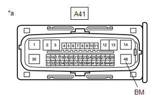
(b) Disconnect the A41 skid control ECU (brake actuator assembly) connector.
(c) Check both the connector case and the terminals for deformation and corrosion.
OK:
No deformation or corrosion.
(d) Measure the voltage according to the value(s) in the table below.
Standard Voltage:
| Tester Connection | Condition | Specified Condition |
|---|---|---|
| A41-46 (BM) - Body ground | Always | 11 to 14 V |
| NG | .gif) | REPAIR OR REPLACE HARNESS OR CONNECTOR |
|
.gif)
| 2. | CHECK HARNESS AND CONNECTOR (GND2 TERMINAL) |
(a) Measure the resistance according to the value(s) in the table below.
Standard Resistance:
| Tester Connection | Condition | Specified Condition |
|---|---|---|
| A41-30 (GND2) - Body ground | 1 minute or more after disconnecting the cable from the negative (-) battery terminal | Below 1 Ω |
| NG | | REPAIR OR REPLACE HARNESS OR CONNECTOR |
|
| 3. | CLEAR DTC |
(a) Reconnect the A41 skid control ECU (brake actuator assembly) connector.
(b) Connect the Techstream to the DLC3.
(c) Turn the engine switch on (IG).
(d) Operate the Techstream to clear the codes. Enter the following menus: Chassis / Brake/EPB / Trouble Codes.
Chassis > Brake/EPB > Clear DTCs(e) Press the DTC clear button.
(f) Turn the engine switch off.
|
| 4. | RECONFIRM DTC |
(a) Start the engine.
(b) Drive the vehicle at a speed of 20 km/h (12 mph).
(c) Read the DTCs following the prompts on the Techstream. Enter the following menus: Chassis / Brake/EPB / Trouble Codes.
Chassis > Brake/EPB > Trouble Codes(d) Check if the same DTC is output.
| Result | Proceed to |
|---|---|
| DTCs C052C13, C052C49 and C052F14 are not output. | A |
| DTCs C052C13, C052C49 and/or C052F14 are output. | B |
HINT:
- If a speed signal of 20 km/h (12 mph) or more is sent to the skid control ECU (brake actuator assembly) with the engine switch on (IG) and the stop light switch assembly off, the ECU performs self diagnosis of the motor and solenoid circuits.
- If the normal system code is output (no DTCs are output), slightly jiggle the connectors, wire harness, and fuses of the skid control ECU (brake actuator assembly).
- If any DTCs are output while jiggling a connector or wire harness of the skid control ECU (brake actuator assembly), inspect and repair the connector or wire harness.
- If no DTCs were output when reconfirming DTCs, checking for intermittent problems is necessary because it is suspected that the original DTCs were stored due to the poor connection of a connector terminal.
| A | | USE SIMULATION METHOD TO CHECK |
| B | | REPLACE BRAKE ACTUATOR ASSEMBLY |
 Steering Angle Sensor Module Component Internal Failure (C052696)
DESCRIPTION The skid control ECU (brake actuator assembly) outputs this DTC when it receives an internal malfunction signal from the steering angle sensor. DTC No. Detection Item DTC Detection ...
 ABS Pump Motor Control Circuit Voltage Out of Range (C052C1C)
DESCRIPTION DTC No. Detection Item DTC Detection Condition Trouble Area C052C1C ABS Pump Motor Control Circuit Voltage Out of Range When the +BS terminal voltage is from 9.5 to 17.4 V ...
Other materials:
Lexus RX (RX 350L, RX450h) 2016-2026 Repair Manual > Climate Control Seat System: Climate Control Seat System does not Operate
DESCRIPTION The air conditioning amplifier assembly receives refreshing seat switch position signals when the engine switch is on (IG), and then transmits airflow amount signals to each seat climate blower. WIRING DIAGRAM CAUTION / NOTICE / HINT NOTICE:
Inspect the fuses for circuits related to ...
Lexus RX (RX 350L, RX450h) 2016-2026 Repair Manual > Meter / Gauge System: Parts Location
PARTS LOCATION ILLUSTRATION *A w/ Adaptive Variable Suspension System - - *1 FUEL SENDER GAUGE ASSEMBLY *2 VACUUM WARNING SWITCH ASSEMBLY *3 LEVEL WARNING SWITCH ASSEMBLY *4 BRAKE ACTUATOR ASSEMBLY - SKID CONTROL ECU *5 BRAKE MASTER CYLINDER RESERVOIR ASSEMBLY - B ...
Lexus RX (RX 350L, RX450h) 2016-{YEAR} Owners Manual
- For your information
- Pictorial index
- For safety and security
- Instrument cluster
- Operation of each component
- Driving
- Lexus Display Audio system
- Interior features
- Maintenance and care
- When trouble arises
- Vehicle specifications
- For owners
Lexus RX (RX 350L, RX450h) 2016-{YEAR} Repair Manual

0.0103