Lexus RX (RX 350L, RX450h) 2016-2026 Repair Manual: ACC Signal Circuit
DESCRIPTION
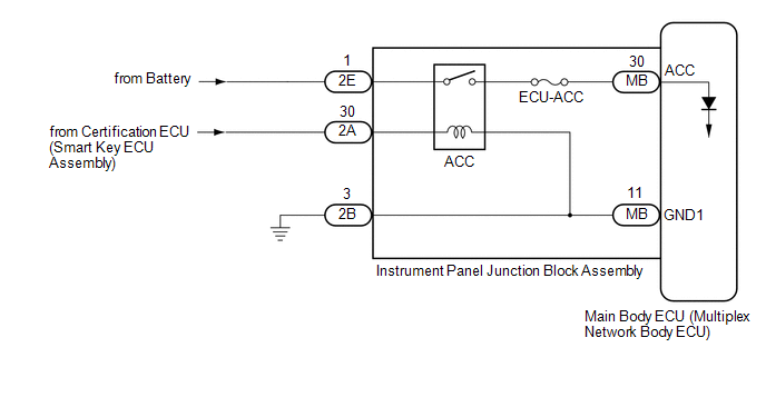
This circuit detects the engine switch on (ACC) or off condition, and sends it to the main body ECU (multiplex network body ECU).
WIRING DIAGRAM
CAUTION / NOTICE / HINT
NOTICE:
- Inspect the fuses for circuits related to this system before performing the following procedure.
-
Before replacing the main body ECU (multiplex network body ECU), refer to Registration.
Click here
.gif)
PROCEDURE
| 1. | CHECK FOR DTC (SMART ACCESS SYSTEM WITH PUSH-BUTTON START (for Start Function)) |
(a) Clear the DTCs.
Click here
(b) Check for the DTCs.
Click here
| Result | Proceed to |
|---|---|
| Smart Access System with Push-button Start (for Start Function) DTCs are not output | A |
| Smart Access System with Push-button Start (for Start Function) DTCs are output | B |
| B | .gif) | GO TO SMART ACCESS SYSTEM WITH PUSH-BUTTON START (for Start Function) |
|
.gif)
| 2. | READ VALUE USING TECHSTREAM |
(a) Connect the Techstream to the DLC3.
(b) Turn the engine switch on (IG).
(c) Turn the Techstream on.
(d) Enter the following menus: Body Electrical / Main Body / Data List.
(e) Read the Data List according to the display on the Techstream.
Body Electrical > Main Body > Data List| Tester Display | Measurement Item | Range | Normal Condition | Diagnostic Note |
|---|---|---|---|---|
| ACC SW | Engine switch on (ACC) signal | ON or OFF | ON: Engine switch on (ACC) OFF: Engine switch off | - |
| Tester Display |
|---|
| ACC SW |
OK:
Normal conditions listed above are displayed.
| OK | | PROCEED TO NEXT SUSPECTED AREA SHOWN IN PROBLEM SYMPTOMS TABLE |
|
| 3. | CHECK HARNESS AND CONNECTOR (POWER SOURCE - INSTRUMENT PANEL JUNCTION BLOCK ASSEMBLY) |
(a) Disconnect the 2E instrument panel junction block assembly connector.
(b) Measure the voltage according to the value(s) in the table below.
Standard Voltage:
| Tester Connection | Condition | Specified Condition |
|---|---|---|
| 2E-1 - Body ground | Always | 11 to 14 V |
| NG | | REPAIR OR REPLACE HARNESS OR CONNECTOR |
|
| 4. | INSPECT INSTRUMENT PANEL JUNCTION BLOCK ASSEMBLY |
(a) Remove the instrument panel junction block assembly.
Click here
(b) Remove the main body ECU (multiplex network body ECU) from the instrument panel junction block assembly.
Click here
(c) Measure the resistance according to the value(s) in the table below.
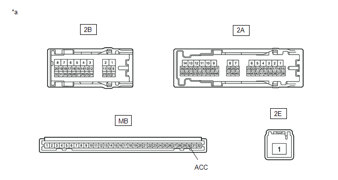
| *a | Component without harness connected (Instrument Panel Junction Block Assembly) | - | - |
Standard Resistance:
| Tester Connection | Condition | Specified Condition |
|---|---|---|
| 2E-1 - MB-30 (ACC) | Battery not connected to 2A-30 and 2B-3 | 10 kΩ or higher |
| 2E-1 - MB-30 (ACC) | Battery positive (+) → 2A-30 Battery negative (-) → 2B-3 | Below 1 Ω |
| OK | | REPLACE MAIN BODY ECU (MULTIPLEX NETWORK BODY ECU) |
| NG | | REPLACE INSTRUMENT PANEL JUNCTION BLOCK ASSEMBLY |
 IG Signal Circuit
DESCRIPTION This circuit detects the engine switch on (IG) or off condition, and sends it to the main body ECU (multiplex network body ECU). WIRING DIAGRAM CAUTION / NOTICE / HINT NOTICE:
Inspect ...
 Door Courtesy Switch Circuit
DESCRIPTION The main body ECU (multiplex network body ECU) detects the condition of the front door courtesy light switch assembly. WIRING DIAGRAM CAUTION / NOTICE / HINT NOTICE: Before replacing the ...
Other materials:
Lexus RX (RX 350L, RX450h) 2016-2026 Repair Manual > Occupant Classification System: Problem Symptoms Table
PROBLEM SYMPTOMS TABLE HINT:
Use the table below to help determine the cause of problem symptoms. If multiple suspected areas are listed, the potential causes of the symptoms are listed in order of probability in the "Suspected Area" column of the table. Check each symptom by checking the suspect ...
Lexus RX (RX 350L, RX450h) 2016-2026 Repair Manual > Safety Connect System: GNSS Antenna Circuit Short to Ground (B15C111,B15C113)
DESCRIPTION These DTCs are stored when a malfunction occurs in the telephone and GPS antenna (for Roof Side) circuit. DTC No. Detection Item DTC Detection Condition Trouble Area B15C111 GNSS Antenna Circuit Short to Ground Current to the GNSS antenna is lower than the malfunction th ...
Lexus RX (RX 350L, RX450h) 2016-{YEAR} Owners Manual
- For your information
- Pictorial index
- For safety and security
- Instrument cluster
- Operation of each component
- Driving
- Lexus Display Audio system
- Interior features
- Maintenance and care
- When trouble arises
- Vehicle specifications
- For owners
Lexus RX (RX 350L, RX450h) 2016-{YEAR} Repair Manual

0.0118