Lexus RX (RX 350L, RX450h) 2016-2026 Repair Manual: Door Courtesy Switch Circuit
DESCRIPTION
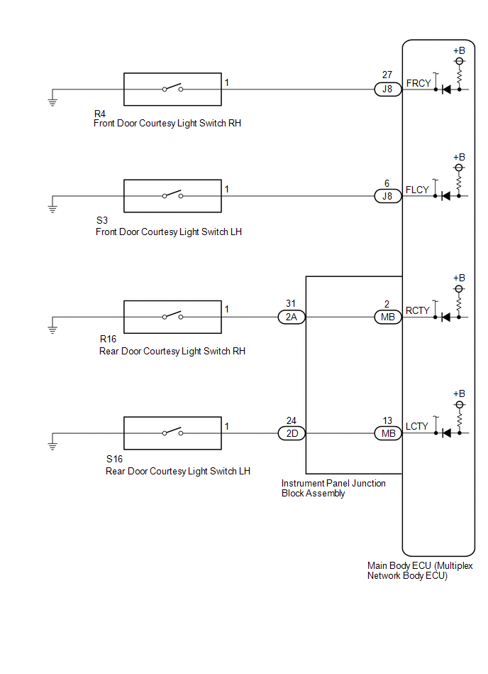
The main body ECU (multiplex network body ECU) detects the condition of the front door courtesy light switch assembly.
WIRING DIAGRAM
CAUTION / NOTICE / HINT
NOTICE:
Before replacing the main body ECU (multiplex network body ECU), refer to Registration.
Click here .gif)
PROCEDURE
| 1. | READ VALUE USING TECHSTREAM |
(a) Connect the Techstream to the DLC3.
(b) Turn the engine switch on (IG).
(c) Turn the Techstream on.
(d) Enter the following menus: Body Electrical / Main Body / Data List.
(e) Read the Data List according to the display on the Techstream.
Body Electrical > Main Body > Data List| Tester Display | Measurement Item | Range | Normal Condition | Diagnostic Note |
|---|---|---|---|---|
| RR Door Courtesy SW | Rear door courtesy light switch assembly RH signal | ON or OFF | ON: Rear door RH open OFF: Rear door RH closed | - |
| RL Door Courtesy SW | Rear door courtesy light switch assembly LH signal | ON or OFF | ON: Rear door LH open OFF: Rear door LH closed | - |
| FR Door Courtesy SW | Front door courtesy light switch assembly RH signal | ON or OFF | ON: Front door RH open OFF: Front door RH closed | - |
| FL Door Courtesy SW | Front door courtesy light switch assembly LH signal | ON or OFF | ON: Front door LH open OFF: Front door LH closed | - |
| Tester Display |
|---|
| RR Door Courtesy SW |
| RL Door Courtesy SW |
| FR Door Courtesy SW |
| FL Door Courtesy SW |
OK:
Normal conditions listed above are displayed.
| Result | Proceed to |
|---|---|
| OK | A |
| FR Door Courtesy SW is not normal | B |
| FL Door Courtesy SW is not normal | C |
| RR Door Courtesy SW is not normal | D |
| RL Door Courtesy SW is not normal | E |
| A | .gif) | PROCEED TO NEXT SUSPECTED AREA SHOWN IN PROBLEM SYMPTOMS TABLE |
| C | | GO TO STEP 4 |
| D | | GO TO STEP 6 |
| E | | GO TO STEP 9 |
|
.gif)
| 2. | INSPECT FRONT DOOR COURTESY LIGHT SWITCH ASSEMBLY RH |
(a) Remove the front door courtesy light switch assembly RH.
Click here
(b) Inspect the front door courtesy light switch assembly RH.
Click here
OK:
Front door courtesy light switch assembly RH is normal.
| NG | | REPLACE FRONT DOOR COURTESY LIGHT SWITCH ASSEMBLY RH |
|
| 3. | CHECK HARNESS AND CONNECTOR (FRONT DOOR COURTESY LIGHT SWITCH ASSEMBLY RH - MAIN BODY ECU (MULTIPLEX NETWORK BODY ECU)) |
(a) Disconnect the J8 main body ECU (multiplex network body ECU) connector.
(b) Measure the resistance according to the value(s) in the table below.
Standard Resistance:
| Tester Connection | Condition | Specified Condition |
|---|---|---|
| R4-1 - J8-27 (FRCY) | Always | Below 1 Ω |
| R4-1 or J8-27 (FRCY) - Body ground | Always | 10 kΩ or higher |
| OK | | REPLACE MAIN BODY ECU (MULTIPLEX NETWORK BODY ECU) |
| NG | | REPAIR OR REPLACE HARNESS OR CONNECTOR |
| 4. | INSPECT FRONT DOOR COURTESY LIGHT SWITCH ASSEMBLY LH |
(a) Remove the front door courtesy light switch assembly LH.
Click here
(b) Inspect the front door courtesy light switch assembly LH.
Click here
OK:
Front door courtesy light switch assembly LH is normal.
| NG | | REPLACE FRONT DOOR COURTESY LIGHT SWITCH ASSEMBLY LH |
|
| 5. | CHECK HARNESS AND CONNECTOR (FRONT DOOR COURTESY LIGHT SWITCH ASSEMBLY LH - MAIN BODY ECU (MULTIPLEX NETWORK BODY ECU)) |
(a) Disconnect the J8 main body ECU (multiplex network body ECU) connector.
(b) Measure the resistance according to the value(s) in the table below.
Standard Resistance:
| Tester Connection | Condition | Specified Condition |
|---|---|---|
| S3-1 - J8-6 (FLCY) | Always | Below 1 Ω |
| S3-1 or J8-6 (FLCY) - Body ground | Always | 10 kΩ or higher |
| OK | | REPLACE MAIN BODY ECU (MULTIPLEX NETWORK BODY ECU) |
| NG | | REPAIR OR REPLACE HARNESS OR CONNECTOR |
| 6. | INSPECT REAR DOOR COURTESY LIGHT SWITCH ASSEMBLY RH |
(a) Remove the rear door courtesy light switch assembly RH.
Click here
(b) Inspect the rear door courtesy light switch assembly RH.
Click here
| NG | | REPLACE REAR DOOR COURTESY LIGHT SWITCH ASSEMBLY RH |
|
| 7. | CHECK HARNESS AND CONNECTOR (REAR DOOR COURTESY LIGHT SWITCH ASSEMBLY RH - INSTRUMENT PANEL JUNCTION BLOCK ASSEMBLY) |
(a) Disconnect the 2A instrument panel junction block assembly connector.
(b) Measure the resistance according to the value(s) in the table below.
Standard Resistance:
| Tester Connection | Condition | Specified Condition |
|---|---|---|
| R16-1 - 2A-31 | Always | Below 1 Ω |
| R16-1 or 2A-31 - Body ground | Always | 10 kΩ or higher |
| NG | | REPAIR OR REPLACE HARNESS OR CONNECTOR |
|
| 8. | INSPECT INSTRUMENT PANEL JUNCTION BLOCK ASSEMBLY |
(a) Remove the instrument panel junction block assembly.
Click here
(b) Remove the main body ECU (multiplex network body ECU) from the instrument panel junction block assembly.
Click here
(c) Measure the resistance according to the value(s) in the table below.
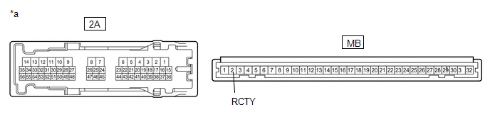
| *a | Component without harness connected (Instrument Panel Junction Block Assembly) | - | - |
Standard Resistance:
| Tester Connection | Condition | Specified Condition |
|---|---|---|
| 2A-31 - MB-2 (RCTY) | Always | Below 1 Ω |
| OK | | REPLACE MAIN BODY ECU (MULTIPLEX NETWORK BODY ECU) |
| NG | | REPLACE INSTRUMENT PANEL JUNCTION BLOCK ASSEMBLY |
| 9. | INSPECT REAR DOOR COURTESY LIGHT SWITCH ASSEMBLY LH |
(a) Remove the rear door courtesy light switch assembly LH.
Click here
(b) Inspect the rear door courtesy light switch assembly LH.
Click here
| NG | | REPLACE REAR DOOR COURTESY LIGHT SWITCH ASSEMBLY LH |
|
| 10. | CHECK HARNESS AND CONNECTOR (REAR DOOR COURTESY LIGHT SWITCH ASSEMBLY LH - INSTRUMENT PANEL JUNCTION BLOCK ASSEMBLY) |
(a) Disconnect the 2D instrument panel junction block assembly connector.
(b) Measure the resistance according to the value(s) in the table below.
Standard Resistance:
| Tester Connection | Condition | Specified Condition |
|---|---|---|
| S16-1 - 2D-24 | Always | Below 1 Ω |
| S16-1 or 2D-24 - Body ground | Always | 10 kΩ or higher |
| NG | | REPAIR OR REPLACE HARNESS OR CONNECTOR |
|
| 11. | INSPECT INSTRUMENT PANEL JUNCTION BLOCK ASSEMBLY |
(a) Remove the instrument panel junction block assembly.
Click here
(b) Remove the main body ECU (multiplex network body ECU) from the instrument panel junction block assembly.
Click here
(c) Measure the resistance according to the value(s) in the table below.
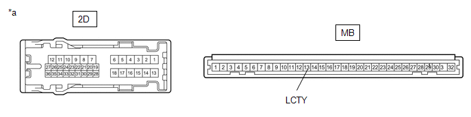
| *a | Component without harness connected (Instrument Panel Junction Block Assembly) | - | - |
Standard Resistance:
| Tester Connection | Condition | Specified Condition |
|---|---|---|
| 2D-24 - MB-13 (LCTY) | Always | Below 1 Ω |
| OK | | REPLACE MAIN BODY ECU (MULTIPLEX NETWORK BODY ECU) |
| NG | | REPLACE INSTRUMENT PANEL JUNCTION BLOCK ASSEMBLY |
 ACC Signal Circuit
DESCRIPTION This circuit detects the engine switch on (ACC) or off condition, and sends it to the main body ECU (multiplex network body ECU). WIRING DIAGRAM CAUTION / NOTICE / HINT NOTICE:
Inspect ...
 Back Door Courtesy Switch Circuit
DESCRIPTION The multiplex network door ECU receives the courtesy light switch signal from the back door lock assembly and transmits it to the main body ECU (multiplex network body ECU) via CAN communi ...
Other materials:
Lexus RX (RX 350L, RX450h) 2016-2026 Repair Manual > Fuel Pump (for High Pressure): On-vehicle Inspection
ON-VEHICLE INSPECTION PROCEDURE 1. FUEL PUMP ASSEMBLY OPERATION (a) Check fuel pressure. (1) Connect the Techstream to the DLC3. (2) Start the engine. (3) Turn the Techstream on. (4) Enter the following menus: Powertrain / Engine / Active Test / Control the Target Fuel Pressure Offset. Powertrain &g ...
Lexus RX (RX 350L, RX450h) 2016-2026 Repair Manual > Navigation / Multi Info Display: Remote Touch
ComponentsCOMPONENTS ILLUSTRATION *1 REAR CONSOLE UPPER PANEL *2 REMOTE OPERATION CONTROLLER ASSEMBLY RemovalREMOVAL PROCEDURE 1. REMOVE REAR CONSOLE UPPER PANEL Click here 2. REMOVE REMOTE OPERATION CONTROLLER ASSEMBLY (a) Remove the 4 screws and remote operation controller assemb ...
Lexus RX (RX 350L, RX450h) 2016-{YEAR} Owners Manual
- For your information
- Pictorial index
- For safety and security
- Instrument cluster
- Operation of each component
- Driving
- Lexus Display Audio system
- Interior features
- Maintenance and care
- When trouble arises
- Vehicle specifications
- For owners
Lexus RX (RX 350L, RX450h) 2016-{YEAR} Repair Manual

0.0103