Lexus RX (RX 350L, RX450h) 2016-2026 Repair Manual: Interior Light Auto Cut Circuit
DESCRIPTION
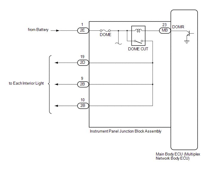
When the battery saving control operates, the main body ECU (multiplex network body ECU) controls the operation of the DOME CUT relay that is built into the instrument panel junction block assembly to turn off the interior lights.
WIRING DIAGRAM
CAUTION / NOTICE / HINT
NOTICE:
- Inspect the fuses for circuits related to this system before performing the following inspection procedure.
-
Before replacing the main body ECU (multiplex network body ECU), refer to Registration.
Click here
.gif)
PROCEDURE
| 1. | PERFORM ACTIVE TEST USING TECHSTREAM |
(a) Connect the Techstream to the DLC3.
(b) Turn the engine switch on (IG).
(c) Turn the Techstream on.
(d) Enter the following menus: Body Electrical / Main Body / Active Test.
(e) Perform the Active Test according to the display on the Techstream.
Body Electrical > Main Body > Active Test| Tester Display | Measurement Item | Control Range | Diagnostic Note |
|---|---|---|---|
| Relay for Interior Light Auto Cut Function | DOME CUT relay | ON or OFF |
|
| Tester Display |
|---|
| Relay for Interior Light Auto Cut Function |
OK:
All of the interior lights turn off when ON is selected.
| OK | .gif) | PROCEED TO NEXT SUSPECTED AREA SHOWN IN PROBLEM SYMPTOMS TABLE |
|
.gif)
| 2. | CHECK HARNESS AND CONNECTOR (POWER SOURCE - INSTRUMENT PANEL JUNCTION BLOCK ASSEMBLY) |
(a) Disconnect the 2E instrument panel junction block assembly connector.
(b) Measure the voltage according to the value(s) in the table below.
Standard Voltage:
| Tester Connection | Condition | Specified Condition |
|---|---|---|
| 2E-1 - Body ground | Always | 11 to 14 V |
| NG | | REPAIR OR REPLACE HARNESS OR CONNECTOR |
|
| 3. | INSPECT INSTRUMENT PANEL JUNCTION BLOCK ASSEMBLY |
(a) Remove the instrument panel junction block assembly.
Click here
(b) Remove the main body ECU (multiplex network body ECU) from the instrument panel junction block assembly.
Click here
(c) Measure the voltage and resistance according to the value(s) in the table below.
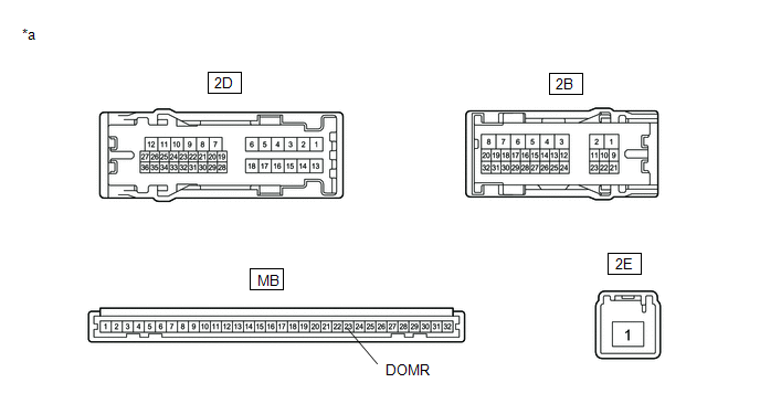
| *a | Component without harness connected (Instrument Panel Junction Block Assembly) | - | - |
Standard Voltage:
| Tester Connection | Condition | Specified Condition |
|---|---|---|
| 2D-19 - Battery negative terminal | Battery positive (+) → 2E-1 Battery negative (-) → MB-23 (DOMR) | 11 to 14 V |
| 2B-9 - Battery negative terminal | Battery positive (+) → 2E-1 Battery negative (-) → MB-23 (DOMR) | 11 to 14 V |
| 2B-10 - Battery negative terminal | Battery positive (+) → 2E-1 Battery negative (-) → MB-23 (DOMR) | 11 to 14 V |
Standard Resistance:
| Tester Connection | Condition | Specified Condition |
|---|---|---|
| 2E-1 - 2D-19 | Always | 10 kΩ or higher |
| 2E-1 - 2B-9 | Always | 10 kΩ or higher |
| 2E-1 - 2B-10 | Always | 10 kΩ or higher |
| OK | | REPLACE MAIN BODY ECU (MULTIPLEX NETWORK BODY ECU) |
| NG | | REPLACE INSTRUMENT PANEL JUNCTION BLOCK ASSEMBLY |
 Interior Light Circuit
DESCRIPTION The main body ECU (multiplex network body ECU) controls the operation of the following lights:
Map Light Assembly (Front Dome Light)
Spot Light Assembly (Rear Dome Light)
Front Door ...
 Interior Light Switch Signal Circuit
DESCRIPTION The main body ECU (multiplex network body ECU) detects the condition of the door switch and front dome light switch. WIRING DIAGRAM CAUTION / NOTICE / HINT NOTICE: Before replacing the ma ...
Other materials:
Lexus RX (RX 350L, RX450h) 2016-2026 Repair Manual > Lighting System (w/ Automatic Headlight Beam Level Control System): Lost Communication With ECM/PCM "A" (U0100,...,U1126)
DESCRIPTION These DTCs are stored if a CAN communication malfunction occurs between the main body ECU (multiplex network body ECU) and other ECUs. DTC No. Detection Item DTC Detection Condition Trouble Area DTC Output from U0100 Lost Communication With ECM/PCM "A" The main body EC ...
Lexus RX (RX 350L, RX450h) 2016-2026 Repair Manual > Smart Access System With Push-button Start (for Entry Function): Dtc Check / Clear
DTC CHECK / CLEAR CHECK FOR DTC NOTICE: When using the Techstream with the engine switch off, connect the Techstream to the DLC3 and turn a courtesy light switch on and off at intervals of 1.5 seconds or less until communication between the Techstream and the vehicle begins. Then select the vehicle ...
Lexus RX (RX 350L, RX450h) 2016-{YEAR} Owners Manual
- For your information
- Pictorial index
- For safety and security
- Instrument cluster
- Operation of each component
- Driving
- Lexus Display Audio system
- Interior features
- Maintenance and care
- When trouble arises
- Vehicle specifications
- For owners
Lexus RX (RX 350L, RX450h) 2016-{YEAR} Repair Manual

0.0107