Lexus RX (RX 350L, RX450h) 2016-2026 Repair Manual: Interior Light Switch Signal Circuit
DESCRIPTION
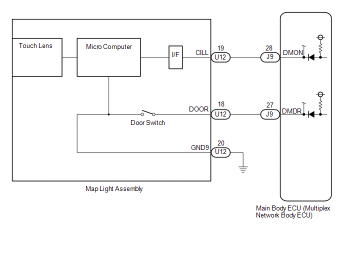
The main body ECU (multiplex network body ECU) detects the condition of the door switch and front dome light switch.
WIRING DIAGRAM
CAUTION / NOTICE / HINT
NOTICE:
Before replacing the main body ECU (multiplex network body ECU), refer to Registration.
Click here .gif)
PROCEDURE
| 1. | READ VALUE USING TECHSTREAM |
(a) Connect the Techstream to the DLC3.
(b) Turn the engine switch on (IG).
(c) Turn the Techstream on.
(d) Enter the following menus: Body Electrical / Main Body / Data List.
(e) Read the Data List according to the display on the Techstream.
Body Electrical > Main Body > Data List| Tester Display | Measurement Item | Range | Normal Condition | Diagnostic Note |
|---|---|---|---|---|
| Dome Light DOOR SW | Door switch signal | ON or OFF | ON: Door switch pressed OFF: Door switch not pressed | - |
| Dome Light SW | Front dome light switch signal | ON or OFF | ON: Front dome light switch ON OFF: Front dome light switch OFF | - |
| Tester Display |
|---|
| Dome Light DOOR SW |
| Dome Light SW |
OK:
Normal conditions listed above are displayed.
| Result | Proceed to |
|---|---|
| OK | A |
| Dome Light DOOR SW is not normal | B |
| Dome Light SW is not normal | C |
| A | .gif) | PROCEED TO NEXT SUSPECTED AREA SHOWN IN PROBLEM SYMPTOMS TABLE |
| C | | GO TO STEP 4 |
|
.gif)
| 2. | INSPECT MAP LIGHT ASSEMBLY |
(a) Remove the map light assembly.
Click here
(b) Inspect the map light assembly.
Click here
OK:
Map light assembly is normal.
| NG | | REPLACE MAP LIGHT ASSEMBLY |
|
| 3. | CHECK HARNESS AND CONNECTOR (MAP LIGHT ASSEMBLY - MAIN BODY ECU (MULTIPLEX NETWORK BODY ECU) AND BODY GROUND) |
(a) Disconnect the J9 main body ECU (multiplex network body ECU) connector.
(b) Measure the resistance according to the value(s) in the table below.
Standard Resistance:
| Tester Connection | Condition | Specified Condition |
|---|---|---|
| U12-18 (DOOR) - J9-27 (DMDR) | Always | Below 1 Ω |
| U12-19 (CILL) - J9-28 (DMON) | Always | Below 1 Ω |
| U12-20 (GND9) - Body ground | Always | Below 1 Ω |
| U12-18 (DOOR) or J9-27 (DMDR) - Body ground | Always | 10 kΩ or higher |
| U12-19 (CILL) or J9-28 (DMON) - Body ground | Always | 10 kΩ or higher |
| OK | | REPLACE MAIN BODY ECU (MULTIPLEX NETWORK BODY ECU) |
| NG | | REPAIR OR REPLACE HARNESS OR CONNECTOR |
| 4. | CHECK HARNESS AND CONNECTOR (MAP LIGHT ASSEMBLY - MAIN BODY ECU (MULTIPLEX NETWORK BODY ECU) AND BODY GROUND) |
(a) Disconnect the J9 main body ECU (multiplex network body ECU) connector.
(b) Disconnect the U12 map light assembly connector.
(c) Measure the resistance according to the value(s) in the table below.
Standard Resistance:
| Tester Connection | Condition | Specified Condition |
|---|---|---|
| U12-19 (CILL) - J9-28 (DMON) | Always | Below 1 Ω |
| U12-20 (GND9) - Body ground | Always | Below 1 Ω |
| U12-19 (CILL) or J9-28 (DMON) - Body ground | Always | 10 kΩ or higher |
| NG | | REPAIR OR REPLACE HARNESS OR CONNECTOR |
|
| 5. | INSPECT MAP LIGHT ASSEMBLY |
(a) Replace the map lamp assembly with a new or known good one.
Click here
(b) Connect the Techstream to the DLC3.
(c) Turn the engine switch on (IG).
(d) Turn the Techstream on.
(e) Enter the following menus: Body Electrical / Main Body / Data List.
(f) Read the Data List according to the display on the Techstream.
Body Electrical > Main Body > Data List| Tester Display | Measurement Item | Range | Normal Condition | Diagnostic Note |
|---|---|---|---|---|
| Dome Light SW | Front dome light switch signal | ON or OFF | ON: Front dome light switch ON OFF: Front dome light switch OFF | - |
| Tester Display |
|---|
| Dome Light SW |
OK:
Normal conditions listed above are displayed.
| Result | Proceed to |
|---|---|
| Dome Light SW is normal | A |
| Dome Light SW is not normal | B |
| A | | END (MAP LAMP ASSEMBLY WAS DEFECTIVE) |
| B | | REPLACE MAIN BODY ECU (MULTIPLEX NETWORK BODY ECU) |
 Interior Light Auto Cut Circuit
DESCRIPTION When the battery saving control operates, the main body ECU (multiplex network body ECU) controls the operation of the DOME CUT relay that is built into the instrument panel junction block ...
 Instrument Panel Box Light and Footwell Light Circuit
DESCRIPTION The main body ECU (multiplex network body ECU) controls the instrument panel box light and footwell light. WIRING DIAGRAM CAUTION / NOTICE / HINT NOTICE: Before replacing the main body EC ...
Other materials:
Lexus RX (RX 350L, RX450h) 2016-2026 Repair Manual > Sfi System: Fuel Level Sensor "A" Signal Stuck In Range (P04602A)
DESCRIPTION Refer to DTC P046012. Click here DTC No. Detection Item DTC Detection Condition Trouble Area MIL Memory Note P04602A Fuel Level Sensor "A" Signal Stuck In Range The change in the fuel sender gauge value is below the threshold when a certain amount of fuel is calc ...
Lexus RX (RX 350L, RX450h) 2016-2026 Repair Manual > Sfi System: Control Module Processor System Internal Failure (P060604,P060629,P060647)
MONITOR DESCRIPTION The ECM continuously monitors its main and sub CPUs. This self-check ensures that the ECM is functioning properly. If outputs from these CPUs are different and deviate from the standard, the ECM will illuminate the MIL and store a DTCs. DTC No. Detection Item DTC Detection ...
Lexus RX (RX 350L, RX450h) 2016-{YEAR} Owners Manual
- For your information
- Pictorial index
- For safety and security
- Instrument cluster
- Operation of each component
- Driving
- Lexus Display Audio system
- Interior features
- Maintenance and care
- When trouble arises
- Vehicle specifications
- For owners
Lexus RX (RX 350L, RX450h) 2016-{YEAR} Repair Manual

0.0114