Lexus RX (RX 350L, RX450h) 2016-2026 Repair Manual: Instrument Panel Box Light and Footwell Light Circuit
DESCRIPTION
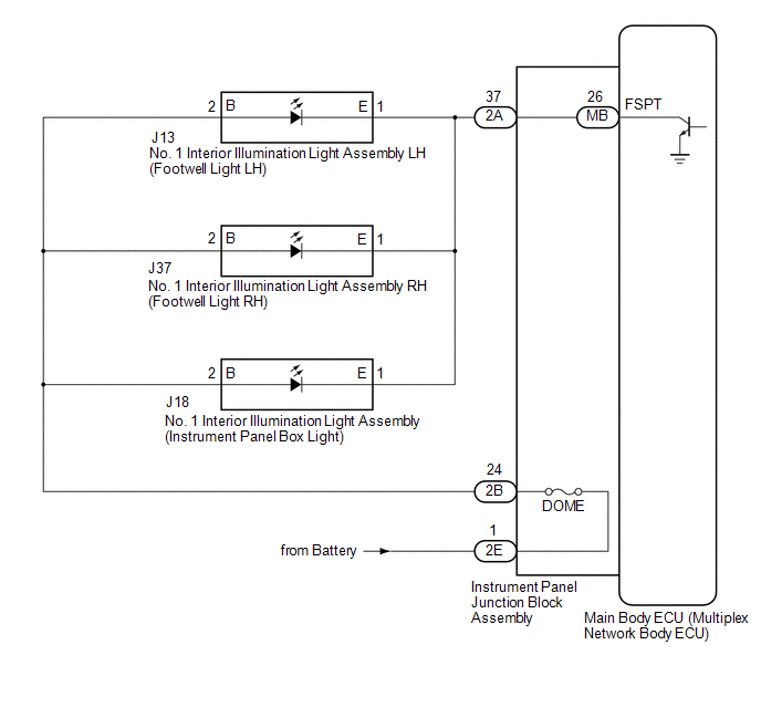
The main body ECU (multiplex network body ECU) controls the instrument panel box light and footwell light.
WIRING DIAGRAM
CAUTION / NOTICE / HINT
NOTICE:
Before replacing the main body ECU (multiplex network body ECU), refer to Registration.
Click here .gif)
PROCEDURE
| 1. | PERFORM ACTIVE TEST USING TECHSTREAM |
(a) Connect the Techstream to the DLC3.
(b) Start the engine.
(c) Turn the Techstream on.
(d) Enter the following menus: Body Electrical / (desired system) / Active Test.
(e) Perform the Active Test according to the display on the Techstream.
Body Electrical > Main Body > Active Test| Tester Display | Measurement Item | Control Range | Diagnostic Note |
|---|---|---|---|
| Fr Foot Light | Footwell light and instrument panel box light | ON or OFF | - |
| Tester Display |
|---|
| Fr Foot Light |
OK:
Instrument panel box light and footwell lights comes on.
| OK | .gif) | PROCEED TO NEXT SUSPECTED AREA SHOWN IN PROBLEM SYMPTOMS TABLE |
|
.gif)
| 2. | CHECK HARNESS AND CONNECTOR (POWER SOURCE - INSTRUMENT PANEL JUNCTION BLOCK ASSEMBLY) |
(a) Disconnect the 2E instrument panel junction block assembly connector.
(b) Measure the voltage according to the value(s) in the table below.
Standard Voltage:
| Tester Connection | Condition | Specified Condition |
|---|---|---|
| 2E-1 - Body ground | Always | 11 to 14 V |
| NG | | REPAIR OR REPLACE HARNESS OR CONNECTOR |
|
| 3. | INSPECT INSTRUMENT PANEL JUNCTION BLOCK ASSEMBLY |
(a) Disconnect the 2E instrument panel junction block assembly connector.
(b) Disconnect the 2B instrument panel junction block assembly connector.
(c) Measure the resistance according to the value(s) in the table below.
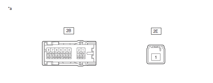
| *a | Component without harness connected (Instrument Panel Junction Block Assembly) | - | - |
Standard Resistance:
| Tester Connection | Condition | Specified Condition |
|---|---|---|
| 2E-1 - 2B-24 | Always | Below 1 Ω |
| NG | | REPLACE INSTRUMENT PANEL JUNCTION BLOCK ASSEMBLY |
|
| 4. | CHECK HARNESS AND CONNECTOR (No. 1 INTERIOR ILLUMINATION LIGHT ASSEMBLY - INSTRUMENT PANEL JUNCTION BLOCK ASSEMBLY) |
(a) Disconnect the J13 No. 1 interior illumination light assembly LH connector.
(b) Disconnect the J37 No. 1 interior illumination light assembly RH connector.
(c) Disconnect the J18 No. 1 interior illumination light assembly connector.
(d) Measure the resistance according to the value(s) in the table below.
Standard Resistance:
| Tester Connection | Condition | Specified Condition |
|---|---|---|
| 2B-24 - J13-2(B) | Always | Below 1 Ω |
| 2B-24 - J37-2(B) | Always | Below 1 Ω |
| 2B-24 - J18-2(B) | Always | Below 1 Ω |
| J13-2(B) or 2B-24 - Body ground | Always | 10 kΩ or higher |
| J37-2(B) or 2B-24 - Body ground | Always | 10 kΩ or higher |
| J18-2(B) or 2B-24 - Body ground | Always | 10 kΩ or higher |
| NG | | REPAIR OR REPLACE HARNESS OR CONNECTOR |
|
| 5. | CHECK HARNESS AND CONNECTOR (No. 1 INTERIOR ILLUMINATION LIGHT ASSEMBLY - INSTRUMENT PANEL JUNCTION BLOCK ASSEMBLY) |
(a) Disconnect the 2A instrument panel junction block assembly connector.
(b) Measure the resistance according to the value(s) in the table below.
Standard Resistance:
| Tester Connection | Condition | Specified Condition |
|---|---|---|
| 2A-37 - J13-1(E) | Always | Below 1 Ω |
| 2A-37 - J37-1(E) | Always | Below 1 Ω |
| 2A-37 - J18-1(E) | Always | Below 1 Ω |
| J13-1(E) or 2A-37 - Body ground | Always | 10 kΩ or higher |
| J37-1(E) or 2A-37 - Body ground | Always | 10 kΩ or higher |
| J18-1(E) or 2A-37 - Body ground | Always | 10 kΩ or higher |
| NG | | REPAIR OR REPLACE HARNESS OR CONNECTOR |
|
| 6. | INSPECT INSTRUMENT PANEL JUNCTION BLOCK ASSEMBLY |
(a) Remove the instrument panel junction block assembly.
Click here
(b) Remove the main body ECU (multiplex network body ECU) from the instrument panel junction block assembly.
Click here
(c) Measure the resistance according to the value(s) in the table below.
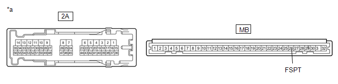
| *a | Component without harness connected (Instrument Panel Junction Block Assembly) | - | - |
Standard Resistance:
| Tester Connection | Condition | Specified Condition |
|---|---|---|
| 2A-37 - MB-26 (FSPT) | Always | Below 1 Ω |
| OK | | REPLACE MAIN BODY ECU (MULTIPLEX NETWORK BODY ECU) |
| NG | | REPLACE INSTRUMENT PANEL JUNCTION BLOCK ASSEMBLY |
 Interior Light Switch Signal Circuit
DESCRIPTION The main body ECU (multiplex network body ECU) detects the condition of the door switch and front dome light switch. WIRING DIAGRAM CAUTION / NOTICE / HINT NOTICE: Before replacing the ma ...
 Ambient Illumination Light Circuit
DESCRIPTION The main body ECU (multiplex network body ECU) controls the ambient illumination lights. WIRING DIAGRAM CAUTION / NOTICE / HINT NOTICE:
Inspect the lights for circuits related to this ...
Other materials:
Lexus RX (RX 350L, RX450h) 2016-2026 Repair Manual > Immobiliser System: Security Indicator Light Does not Blink
DESCRIPTION
The certification ECU (smart key ECU assembly) blinks the security indicator light (radio receiver assembly) when the immobiliser is set (engine switch off).
The certification ECU (smart key ECU assembly) receives the security indicator light signal from the main body ECU (multiplex ...
Lexus RX (RX 350L, RX450h) 2016-2026 Repair Manual > Blower Unit: Installation
INSTALLATION PROCEDURE 1. INSTALL CLEAN AIR FILTER (a) Engage the 4 guides as indicated by the arrows, in the order shown in the illustration to install the clean air filter to the air filter case. Install in this Direction (1) Install in this Direction (2) NOTICE: Make sure that the ...
Lexus RX (RX 350L, RX450h) 2016-{YEAR} Owners Manual
- For your information
- Pictorial index
- For safety and security
- Instrument cluster
- Operation of each component
- Driving
- Lexus Display Audio system
- Interior features
- Maintenance and care
- When trouble arises
- Vehicle specifications
- For owners
Lexus RX (RX 350L, RX450h) 2016-{YEAR} Repair Manual

0.011