Lexus RX (RX 350L, RX450h) 2016-2026 Repair Manual: Ambient Illumination Light Circuit
DESCRIPTION
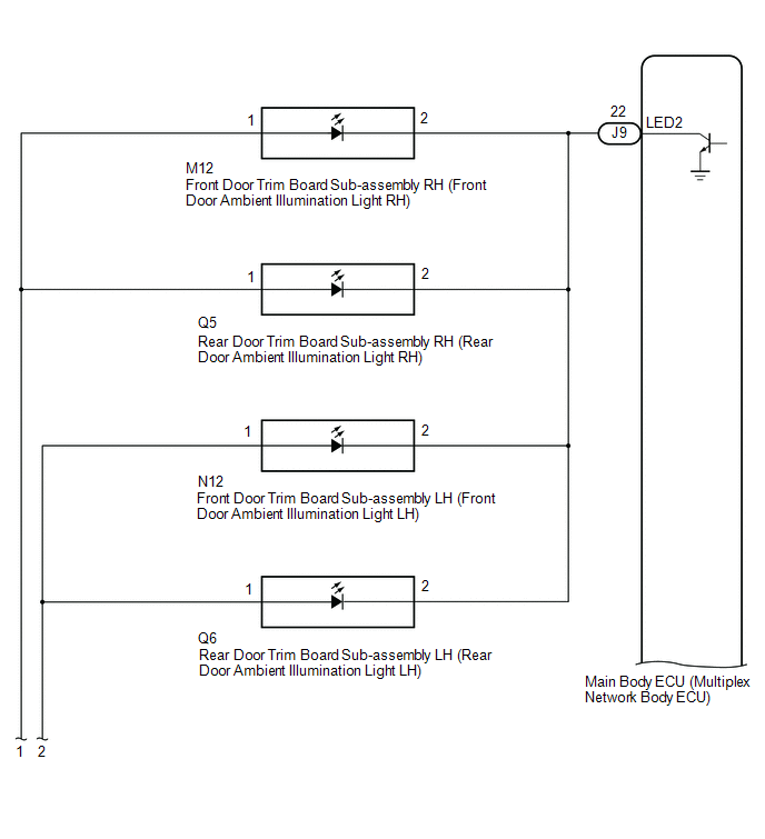
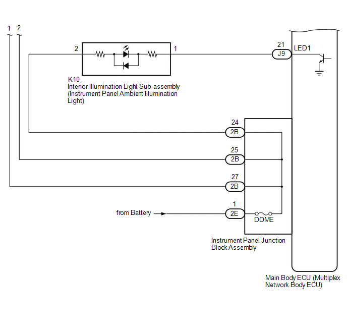
The main body ECU (multiplex network body ECU) controls the ambient illumination lights.
WIRING DIAGRAM
CAUTION / NOTICE / HINT
NOTICE:
- Inspect the lights for circuits related to this system before performing the following procedure.
-
Before replacing the main body ECU (multiplex network body ECU), refer to Registration.
Click here
.gif)
PROCEDURE
| 1. | PERFORM ACTIVE TEST USING TECHSTREAM |
(a) Connect the Techstream to the DLC3.
(b) Turn the engine switch on (IG).
(c) Turn the Techstream on.
(d) Enter the following menus: Body Electrical / Main Body / Active Test.
(e) Perform the Active Test according to the display on the Techstream.
Body Electrical > Main Body > Active Test| Tester Display | Measurement Item | Control Range | Diagnostic Note |
|---|---|---|---|
| Interior Illumination Light1 | Instrument panel ambient illumination light | ON or OFF | Preconditions for using the Active Test to check dimmer controlled illumination:
|
| Interior Illumination Light2 | Door ambient illumination light | ON or OFF | Preconditions for using the Active Test to check dimmer controlled illumination:
|
| Tester Display |
|---|
| Interior Illumination Light1 |
| Tester Display |
|---|
| Interior Illumination Light2 |
OK:
Instrument panel ambient illumination light and door ambient illumination lights comes on.
| Result | Proceed to |
|---|---|
| OK | A |
| NG (All ambient lights do not illuminate) | B |
| NG (Instrument panel ambient illumination light does not illuminate) | C |
| NG (Door ambient illumination light does not illuminate) | D |
| A | .gif) | PROCEED TO NEXT SUSPECTED AREA SHOWN IN PROBLEM SYMPTOMS TABLE |
| C | | GO TO STEP 4 |
| D | | GO TO STEP 7 |
|
.gif)
| 2. | CHECK HARNESS AND CONNECTOR (POWER SOURCE - INSTRUMENT PANEL JUNCTION BLOCK ASSEMBLY) |
(a) Disconnect the 2E instrument panel junction block assembly connector.
(b) Measure the voltage according to the value(s) in the table below.
Standard Voltage:
| Tester Connection | Condition | Specified Condition |
|---|---|---|
| 2E-1 - Body ground | Always | 11 to 14 V |
| NG | | REPAIR OR REPLACE HARNESS OR CONNECTOR |
|
| 3. | INSPECT INSTRUMENT PANEL JUNCTION BLOCK ASSEMBLY |
(a) Disconnect the 2B instrument panel junction block assembly connector.
(b) Measure the resistance according to the value(s) in the table below.
.png)
| *a | Component without harness connected (Instrument Panel Junction Block Assembly) | - | - |
Standard Resistance:
| Tester Connection | Condition | Specified Condition |
|---|---|---|
| 2E-1 - 2B-24 | Always | Below 1 Ω |
| 2E-1 - 2B-25 | Always | Below 1 Ω |
| 2E-1 - 2B-27 | Always | Below 1 Ω |
| OK | | PROCEED TO NEXT SUSPECTED AREA SHOWN IN PROBLEM SYMPTOMS TABLE |
| NG | | REPLACE INSTRUMENT PANEL JUNCTION BLOCK ASSEMBLY |
| 4. | INSPECT INSTRUMENT PANEL JUNCTION BLOCK ASSEMBLY |
(a) Disconnect the 2B and 2E instrument panel junction block assembly connector.
(b) Measure the resistance according to the value(s) in the table below.
| *a | Component without harness connected (Instrument Panel Junction Block Assembly) | - | - |
Standard Resistance:
| Tester Connection | Condition | Specified Condition |
|---|---|---|
| 2E-1 - 2B-24 | Always | Below 1 Ω |
| NG | | REPLACE INSTRUMENT PANEL JUNCTION BLOCK ASSEMBLY |
|
| 5. | CHECK HARNESS AND CONNECTOR (INTERIOR ILLUMINATION LIGHT SUB-ASSEMBLY - INSTRUMENT PANEL JUNCTION BLOCK ASSEMBLY) |
(a) Disconnect the K10 interior illumination light sub-assembly connector.
(b) Measure the resistance according to the value(s) in the table below.
Standard Resistance:
| Tester Connection | Condition | Specified Condition |
|---|---|---|
| K10-2 - 2B-24 | Always | Below 1 Ω |
| K10-2 or 2B-24 - Body ground | Always | 10 kΩ or higher |
| NG | | REPAIR OR REPLACE HARNESS OR CONNECTOR |
|
| 6. | CHECK HARNESS AND CONNECTOR (INTERIOR ILLUMINATION LIGHT SUB-ASSEMBLY - MAIN BODY ECU (MULTIPLEX NETWORK BODY ECU)) |
(a) Disconnect the J9 main body ECU (multiplex network body ECU) connector.
(b) Measure the resistance according to the value(s) in the table below.
Standard Resistance:
| Tester Connection | Condition | Specified Condition |
|---|---|---|
| K10-1 - J9-21 (LED1) | Always | Below 1 Ω |
| K10-1 or J9-21 (LED1) - Body ground | Always | 10 kΩ or higher |
| OK | | REPLACE MAIN BODY ECU (MULTIPLEX NETWORK BODY ECU) |
| NG | | REPAIR OR REPLACE HARNESS OR CONNECTOR |
| 7. | INSPECT INSTRUMENT PANEL JUNCTION BLOCK ASSEMBLY |
(a) Disconnect the 2B and 2E instrument panel junction block assembly connector.
(b) Measure the resistance according to the value(s) in the table below.
| *a | Component without harness connected (Instrument Panel Junction Block Assembly) | - | - |
Standard Resistance:
| Tester Connection | Condition | Specified Condition |
|---|---|---|
| 2E-1 - 2B-25 | Always | Below 1 Ω |
| 2E-1 - 2B-27 | Always | Always |
| NG | | REPLACE INSTRUMENT PANEL JUNCTION BLOCK ASSEMBLY |
|
| 8. | CHECK HARNESS AND CONNECTOR (DOOR TRIM BOARD SUB-ASSEMBLY - INSTRUMENT PANEL JUNCTION BLOCK ASSEMBLY) |
(a) Disconnect the M12 front door trim board sub-assembly RH connector.
(b) Disconnect the N12 front door trim board sub-assembly LH connector.
(c) Disconnect the Q5 rear door trim board sub-assembly RH connector.
(d) Disconnect the Q6 rear door trim board sub-assembly LH connector.
(e) Measure the resistance according to the value(s) in the table below.
Standard Resistance:
| Tester Connection | Condition | Specified Condition |
|---|---|---|
| M12-1 - 2B-27 | Always | Below 1 Ω |
| M12-1 or 2B-27 - Body ground | Always | 10 kΩ or higher |
| Q5-1 - 2B-27 | Always | Below 1 Ω |
| Q5-1 or 2B-27 - Body ground | Always | 10 kΩ or higher |
| N12-1 - 2B-25 | Always | Below 1 Ω |
| N12-1 or 2B-25 - Body ground | Always | 10 kΩ or higher |
| Q6-1 - 2B-25 | Always | Below 1 Ω |
| Q6-1 or 2B-25 - Body ground | Always | 10 kΩ or higher |
| NG | | REPAIR OR REPLACE HARNESS OR CONNECTOR |
|
| 9. | CHECK HARNESS AND CONNECTOR (DOOR TRIM BOARD SUB-ASSEMBLY - MAIN BODY ECU (MULTIPLEX NETWORK BODY ECU)) |
(a) Disconnect the J9 main body ECU (multiplex network body ECU) connector.
(b) Measure the resistance according to the value(s) in the table below.
Standard Resistance:
| Tester Connection | Condition | Specified Condition |
|---|---|---|
| M12-2 - J9-22 (LED2) | Always | Below 1 Ω |
| M12-2 or J9-22 (LED2) - Body ground | Always | 10 kΩ or higher |
| Q5-2 - J9-22 (LED2) | Always | Below 1 Ω |
| Q5-2 or J9-22 (LED2) - Body ground | Always | 10 kΩ or higher |
| N12-2 - J9-22 (LED2) | Always | Below 1 Ω |
| N12-2 or J9-22 (LED2) - Body ground | Always | 10 kΩ or higher |
| Q6-2 - J9-22 (LED2) | Always | Below 1 Ω |
| Q6-2 or J9-22 (LED2) - Body ground | Always | 10 kΩ or higher |
| OK | | REPLACE MAIN BODY ECU (MULTIPLEX NETWORK BODY ECU) |
| NG | | REPAIR OR REPLACE HARNESS OR CONNECTOR |
 Instrument Panel Box Light and Footwell Light Circuit
DESCRIPTION The main body ECU (multiplex network body ECU) controls the instrument panel box light and footwell light. WIRING DIAGRAM CAUTION / NOTICE / HINT NOTICE: Before replacing the main body EC ...
 Engine Switch Illumination Circuit
DESCRIPTION The illuminated entry system controls the engine switch illumination. WIRING DIAGRAM PROCEDURE 1. PERFORM ACTIVE TEST USING TECHSTREAM (a) Connect the Techstream to the DLC3. (b) ...
Other materials:
Lexus RX (RX 350L, RX450h) 2016-2026 Repair Manual > Steering Heater Switch: Removal
REMOVAL PROCEDURE 1. REMOVE INSTRUMENT PANEL GARNISH LH Click here 2. REMOVE FRONT DOOR SCUFF PLATE LH w/ Rear No. 2 Seat: Click here w/o Rear No. 2 Seat: Click here 3. REMOVE COWL SIDE TRIM BOARD LH Click here 4. REMOVE NO. 1 INSTRUMENT PANEL UNDER COVER SUB-ASSEMBLY Click here 5. DI ...
Lexus RX (RX 350L, RX450h) 2016-2026 Repair Manual > Steering Lock System: IG2 Signal Malfunction (B2788)
DESCRIPTION This DTC is stored when the steering lock ECU (steering lock actuator or upper bracket assembly) detects an IG2 power supply malfunction. HINT: The steering lock ECU (steering lock actuator or upper bracket assembly) is not connected to the CAN communication system. However, the steering ...
Lexus RX (RX 350L, RX450h) 2016-{YEAR} Owners Manual
- For your information
- Pictorial index
- For safety and security
- Instrument cluster
- Operation of each component
- Driving
- Lexus Display Audio system
- Interior features
- Maintenance and care
- When trouble arises
- Vehicle specifications
- For owners
Lexus RX (RX 350L, RX450h) 2016-{YEAR} Repair Manual

0.0206