Lexus RX (RX 350L, RX450h) 2016-2026 Repair Manual: Door Unlock Detection Switch Circuit
DESCRIPTION
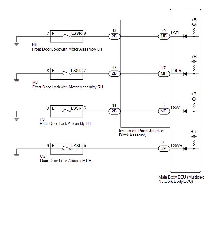
The main body ECU (multiplex network body ECU) detects the condition of each door unlock detection switch.
WIRING DIAGRAM
CAUTION / NOTICE / HINT
NOTICE:
Before replacing the main body ECU (multiplex network body ECU), refer to Registration.
Click here .gif)
PROCEDURE
| 1. | READ VALUE USING TECHSTREAM |
(a) Connect the Techstream to the DLC3.
(b) Turn the engine switch on (IG).
(c) Turn the Techstream on.
(d) Enter the following menus: Body Electrical / Main Body / Data List.
(e) Read the Data List according to the display on the Techstream.
Body Electrical > Main Body > Data List| Tester Display | Measurement Item | Range | Normal Condition | Diagnostic Note |
|---|---|---|---|---|
| FR Door Lock Pos | Front door RH unlock detection switch signal | LOCK or UNLOCK | LOCK: Front door RH locked UNLOCK: Front door RH unlocked | - |
| FL Door Lock Pos | Front door LH unlock detection switch signal | LOCK or UNLOCK | LOCK: Front door LH locked UNLOCK: Front door LH unlocked | - |
| RR-Door Lock Pos SW | Rear door RH unlock detection switch signal | ON or OFF | ON: Rear door RH unlocked OFF: Rear door RH locked | - |
| RL-Door Lock Pos SW | Rear door LH unlock detection switch signal | ON or OFF | ON: Rear door LH unlocked OFF: Rear door LH locked | - |
| Tester Display |
|---|
| FR Door Lock Pos |
| FL Door Lock Pos |
| RR-Door Lock Pos SW |
| RL-Door Lock Pos SW |
| Result | Proceed to |
|---|---|
| OK | A |
| FL Door Lock Pos is not normal | B |
| FR Door Lock Pos is not normal | C |
| RL-Door Lock Pos SW is not normal | D |
| RR-Door Lock Pos SW is not normal | E |
| A | .gif) | PROCEED TO NEXT SUSPECTED AREA SHOWN IN PROBLEM SYMPTOMS TABLE |
| C | | GO TO STEP 5 |
| D | | GO TO STEP 8 |
| E | | GO TO STEP 11 |
|
.gif)
| 2. | INSPECT FRONT DOOR LOCK WITH MOTOR ASSEMBLY LH |
(a) Remove the front door lock with motor assembly LH.
Click here
(b) Inspect the front door lock with motor assembly LH.
Click here
OK:
Front door lock with motor assembly LH is normal.
| NG | | REPLACE FRONT DOOR LOCK WITH MOTOR ASSEMBLY LH |
|
| 3. | CHECK HARNESS AND CONNECTOR (FRONT DOOR LOCK WITH MOTOR ASSEMBLY LH - INSTRUMENT PANEL JUNCTION BLOCK ASSEMBLY OR BODY GROUND) |
(a) Disconnect the 2B instrument panel junction block assembly connector.
(b) Measure the resistance according to the value(s) in the table below.
Standard Resistance:
| Tester Connection | Condition | Specified Condition |
|---|---|---|
| N8-8 (LSSR) - 2B-13 | Always | Below 1 Ω |
| N8-8 (LSSR) or 2B-13 - Body ground | Always | 10 kΩ or higher |
| N8-7 (E) - Body ground | Always | Below 1 Ω |
| NG | | REPAIR OR REPLACE HARNESS OR CONNECTOR |
|
| 4. | INSPECT INSTRUMENT PANEL JUNCTION BLOCK ASSEMBLY |
(a) Remove the instrument panel junction block assembly.
Click here
(b) Remove the main body ECU (multiplex network body ECU) from the instrument panel junction block assembly.
Click here
(c) Measure the resistance according to the value(s) in the table below.
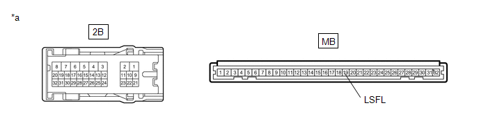
| *a | Component without harness connected (Instrument Panel Junction Block Assembly) | - | - |
Standard Resistance:
| Tester Connection | Condition | Specified Condition |
|---|---|---|
| MB-19 (LSFL) - 2B-13 | Always | Below 1 Ω |
| OK | | REPLACE MAIN BODY ECU (MULTIPLEX NETWORK BODY ECU) |
| NG | | REPLACE INSTRUMENT PANEL JUNCTION BLOCK ASSEMBLY |
| 5. | INSPECT FRONT DOOR LOCK WITH MOTOR ASSEMBLY RH |
(a) Remove the front door lock with motor assembly RH.
Click here
(b) Inspect the front door lock with motor assembly RH.
Click here
OK:
Front door lock with motor assembly RH is normal.
| NG | | REPLACE FRONT DOOR LOCK WITH MOTOR ASSEMBLY RH |
|
| 6. | CHECK HARNESS AND CONNECTOR (FRONT DOOR LOCK WITH MOTOR ASSEMBLY RH - INSTRUMENT PANEL JUNCTION BLOCK ASSEMBLY OR BODY GROUND) |
(a) Disconnect the 2B instrument panel junction block assembly connector.
(b) Measure the resistance according to the value(s) in the table below.
Standard Resistance:
| Tester Connection | Condition | Specified Condition |
|---|---|---|
| M8-7 (LSSR) - 2B-12 | Always | Below 1 Ω |
| M8-7 (LSSR) or 2B-12 - Body ground | Always | 10 kΩ or higher |
| M8-8 (E) - Body ground | Always | Below 1 Ω |
| NG | | REPAIR OR REPLACE HARNESS OR CONNECTOR |
|
| 7. | INSPECT INSTRUMENT PANEL JUNCTION BLOCK ASSEMBLY |
(a) Remove the instrument panel junction block assembly.
Click here
(b) Remove the main body ECU (multiplex network body ECU) from the instrument panel junction block assembly.
Click here
(c) Measure the resistance according to the value(s) in the table below.
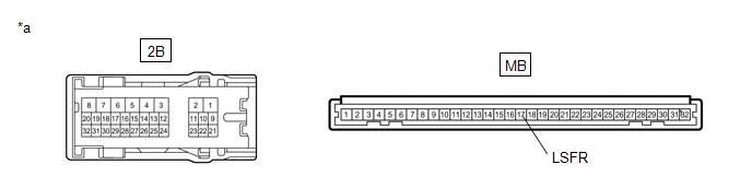
| *a | Component without harness connected (Instrument Panel Junction Block Assembly) | - | - |
Standard Resistance:
| Tester Connection | Condition | Specified Condition |
|---|---|---|
| MB-17 (LSFR) - 2B-12 | Always | Below 1 Ω |
| OK | | REPLACE MAIN BODY ECU (MULTIPLEX NETWORK BODY ECU) |
| NG | | REPLACE INSTRUMENT PANEL JUNCTION BLOCK ASSEMBLY |
| 8. | INSPECT REAR DOOR LOCK ASSEMBLY LH |
(a) Remove the rear door lock assembly LH.
Click here
(b) Inspect the rear door lock assembly LH.
Click here
| NG | | REPLACE REAR DOOR LOCK ASSEMBLY LH |
|
| 9. | CHECK HARNESS AND CONNECTOR (REAR DOOR LOCK ASSEMBLY LH - INSTRUMENT PANEL JUNCTION BLOCK ASSEMBLY OR BODY GROUND) |
(a) Disconnect the 2B instrument panel junction block assembly connector.
(b) Measure the resistance according to the value(s) in the table below.
Standard Resistance:
| Tester Connection | Condition | Specified Condition |
|---|---|---|
| P3-6 (LSSR) - 2B-14 | Always | Below 1 Ω |
| P3-6 (LSSR) or 2B-14 - Body ground | Always | 10 kΩ or higher |
| P3-9 (E) - Body ground | Always | Below 1 Ω |
| NG | | REPAIR OR REPLACE HARNESS OR CONNECTOR |
|
| 10. | INSPECT INSTRUMENT PANEL JUNCTION BLOCK ASSEMBLY |
(a) Remove the instrument panel junction block assembly.
Click here
(b) Remove the main body ECU (multiplex network body ECU) from the instrument panel junction block assembly.
Click here
(c) Measure the resistance according to the value(s) in the table below.
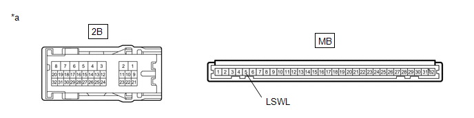
| *a | Component without harness connected (Instrument Panel Junction Block Assembly) | - | - |
Standard Resistance:
| Tester Connection | Condition | Specified Condition |
|---|---|---|
| MB-5 (LSWL) - 2B-14 | Always | Below 1 Ω |
| OK | | REPLACE MAIN BODY ECU (MULTIPLEX NETWORK BODY ECU) |
| NG | | REPLACE INSTRUMENT PANEL JUNCTION BLOCK ASSEMBLY |
| 11. | INSPECT REAR DOOR LOCK ASSEMBLY RH |
(a) Remove the rear door lock assembly RH.
Click here
(b) Inspect the rear door lock assembly RH.
Click here
| NG | | REPLACE REAR DOOR LOCK ASSEMBLY RH |
|
| 12. | CHECK HARNESS AND CONNECTOR (REAR DOOR LOCK ASSEMBLY RH - MAIN BODY ECU (MULTIPLEX NETWORK BODY ECU) OR BODY GROUND) |
(a) Disconnect the J9 main body ECU (multiplex network body ECU) connector.
(b) Measure the resistance according to the value(s) in the table below.
Standard Resistance:
| Tester Connection | Condition | Specified Condition |
|---|---|---|
| O3-6 (LSSR) - J9-2 (LSWR) | Always | Below 1 Ω |
| O3-6 (LSSR) or J9-2 (LSWR) - Body ground | Always | 10 kΩ or higher |
| O3-9 (E) - Body ground | Always | Below 1 Ω |
| OK | | REPLACE MAIN BODY ECU (MULTIPLEX NETWORK BODY ECU) |
| NG | | REPAIR OR REPLACE HARNESS OR CONNECTOR |
 Engine Switch Illumination Circuit
DESCRIPTION The illuminated entry system controls the engine switch illumination. WIRING DIAGRAM PROCEDURE 1. PERFORM ACTIVE TEST USING TECHSTREAM (a) Connect the Techstream to the DLC3. (b) ...
 Luggage Compartment Room Light
ComponentsCOMPONENTS ILLUSTRATION *A for Back Door *B for RH Side *C for LH Side - - *1 NO. 1 LUGGAGE COMPARTMENT LIGHT ASSEMBLY - - InspectionINSPECTION PROCEDURE 1. ...
Other materials:
Lexus RX (RX 350L, RX450h) 2016-2026 Repair Manual > Washer Nozzle(for Rear Side): Removal
REMOVAL PROCEDURE 1. REMOVE REAR SPOILER SUB-ASSEMBLY Click here 2. REMOVE REAR WASHER NOZZLE (a) Disconnect the rear washer hose. *A w/o Rear No. 2 Seat *B w/ Rear No. 2 Seat (b) Disengage the 2 claws to remove the rear washer nozzle. ...
Lexus RX (RX 350L, RX450h) 2016-2026 Repair Manual > Electric Parking Brake System: Right Electric Parking Brake Actuator Signal Stuck In Range (C06132A)
DESCRIPTION DTC No. Detection Item DTC Detection Condition Trouble Area Memory Note C06132A Right Electric Parking Brake Actuator Signal Stuck In Range
Diagnosis Condition:
Electric parking brake operating
Malfunction Status:
Motor locked, gear locked, free spinning
Detec ...
Lexus RX (RX 350L, RX450h) 2016-{YEAR} Owners Manual
- For your information
- Pictorial index
- For safety and security
- Instrument cluster
- Operation of each component
- Driving
- Lexus Display Audio system
- Interior features
- Maintenance and care
- When trouble arises
- Vehicle specifications
- For owners
Lexus RX (RX 350L, RX450h) 2016-{YEAR} Repair Manual

0.0087