Lexus RX (RX 350L, RX450h) 2016-2026 Repair Manual: Luggage Compartment Room Light
Components
COMPONENTS
ILLUSTRATION
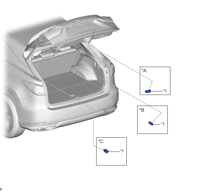
| *A | for Back Door | *B | for RH Side |
| *C | for LH Side | - | - |
| *1 | NO. 1 LUGGAGE COMPARTMENT LIGHT ASSEMBLY | - | - |
Inspection
INSPECTION
PROCEDURE
1. INSPECT NO. 1 LUGGAGE COMPARTMENT LIGHT ASSEMBLY
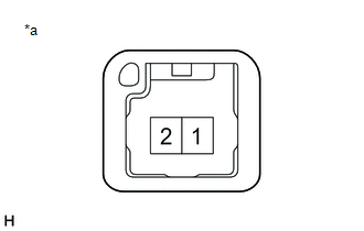
| (a) Inspect the luggage compartment room light. (1) Apply battery voltage to each terminal of No. 1 luggage compartment light assembly connector and check the operation of the luggage compartment room light. Result:
If the result is not as specified, replace the No. 1 luggage compartment light assembly. |
|
Removal
REMOVAL
PROCEDURE
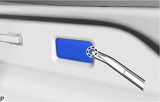
1. REMOVE NO. 1 LUGGAGE COMPARTMENT LIGHT ASSEMBLY (for LH Side)
(a) w/o Rear No. 2 Seat:
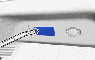
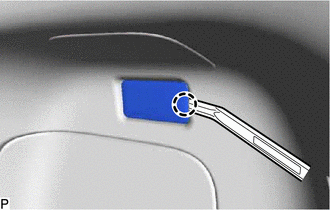
| (1) Using a moulding remover, disengage the claw. |
|
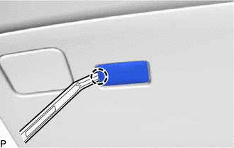
(b) w/ Rear No. 2 Seat:
| (1) Using a moulding remover, disengage the claw. |
|
(c) Disconnect the connector to remove the No. 1 luggage compartment light assembly.
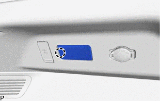
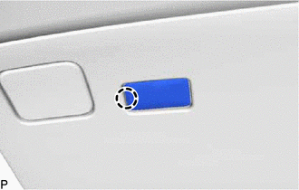
2. REMOVE NO. 1 LUGGAGE COMPARTMENT LIGHT ASSEMBLY (for RH Side)
| (a) Using a moulding remover, disengage the claw. |
|
(b) Disconnect the connector to remove the No. 1 luggage compartment light assembly.
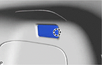
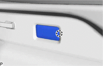
3. REMOVE NO. 1 LUGGAGE COMPARTMENT LIGHT ASSEMBLY (for Back Door)
| (a) Using a moulding remover, disengage the claw. |
|
(b) Disconnect the connector to remove the No. 1 luggage compartment light assembly.
Installation
INSTALLATION
PROCEDURE
1. INSTALL NO. 1 LUGGAGE COMPARTMENT LIGHT ASSEMBLY (for LH Side)
(a) Connect the connector.
(b) w/o Rear No. 2 Seat:
| (1) Engage the claw to install the No. 1 luggage compartment light assembly. |
|
(c) w/ Rear No. 2 Seat:
| (1) Engage the claw to install the No. 1 luggage compartment light assembly. |
|
2. INSTALL NO. 1 LUGGAGE COMPARTMENT LIGHT ASSEMBLY (for RH Side)
(a) Connect the connector.
| (b) Engage the claw to install the No. 1 luggage compartment light assembly. |
|
3. INSTALL NO. 1 LUGGAGE COMPARTMENT LIGHT ASSEMBLY (for Back Door)
(a) Connect the connector.
| (b) Engage the claw to install the No. 1 luggage compartment light assembly. |
|
 Door Unlock Detection Switch Circuit
DESCRIPTION The main body ECU (multiplex network body ECU) detects the condition of each door unlock detection switch. WIRING DIAGRAM CAUTION / NOTICE / HINT NOTICE: Before replacing the main body EC ...
 Personal Light
...
Other materials:
Lexus RX (RX 350L, RX450h) 2016-2026 Repair Manual > Drive Shaft / Propeller Shaft: Propeller Shaft System
Problem Symptoms TablePROBLEM SYMPTOMS TABLE HINT: Use the table below to help determine the cause of problem symptoms. If multiple suspected areas are listed, the potential causes of the symptoms are listed in order of probability in the "Suspected Area" column of the table. Check each symptom by c ...
Lexus RX (RX 350L, RX450h) 2016-2026 Repair Manual > Power Steering System: IG Power Supply Voltage (C1551)
DESCRIPTION The power steering ECU assembly distinguishes the engine switch status as on (IG) or off through the IG power source circuit. DTC No. Detection Item DTC Detection Condition Trouble Area Warning Indicate Return-to-normal Condition Note C1551 IG Power Supply Voltage ...
Lexus RX (RX 350L, RX450h) 2016-{YEAR} Owners Manual
- For your information
- Pictorial index
- For safety and security
- Instrument cluster
- Operation of each component
- Driving
- Lexus Display Audio system
- Interior features
- Maintenance and care
- When trouble arises
- Vehicle specifications
- For owners
Lexus RX (RX 350L, RX450h) 2016-{YEAR} Repair Manual

0.0113