Lexus RX (RX 350L, RX450h) 2016-2026 Repair Manual: Room Light
Components
COMPONENTS
ILLUSTRATION
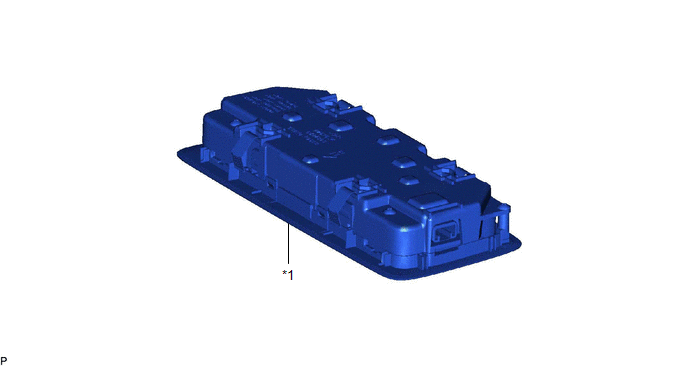
| *1 | SPOT LIGHT ASSEMBLY | - | - |
Inspection
INSPECTION
PROCEDURE
1. INSPECT SPOT LIGHT ASSEMBLY
(a) Inspect the rear dome light.
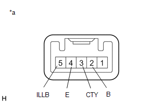
| (1) Apply battery voltage to the connector and check that the rear map light comes on. OK:
If the result is not as specified, replace the spot light assembly. |
|
(b) Inspect the switch illumination.
(1) Apply battery voltage to the connector and check that the switch illumination comes on.
OK:
| Measurement Condition | Condition | Specified Condition |
|---|---|---|
| Battery positive (+) → 5 (ILLB) Battery negative (-) → 4 (E) | Always | Switch illumination comes on |
If the result is not as specified, replace the spot light assembly.
Removal
REMOVAL
PROCEDURE
1. REMOVE SPOT LIGHT ASSEMBLY
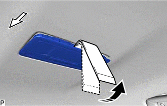
(a) Using the moulding remover D as shown in the illustration, raise the roof headlining assembly until the clip of the spot light assembly can be seen.
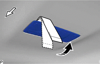
.png) | Front |
.png) | Move in this Direction |
NOTICE:
Be careful not to damage the roof headlining assembly.
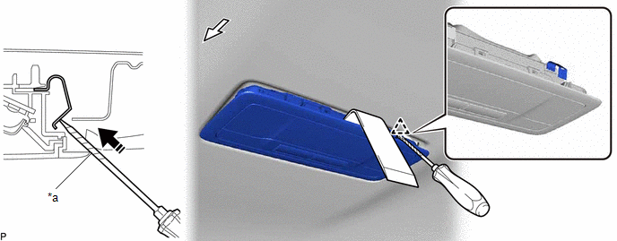
(b) While continuing to hold the moulding remover D, disengage the clip using a screwdriver wrapped with protective tape.
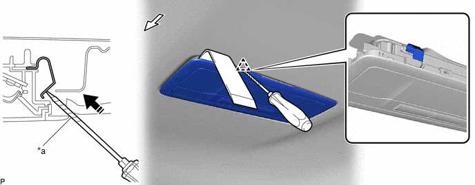
| *a | Protective Tape | - | - |
| | Front | | Push in this Direction |
NOTICE:
Be careful not to damage the roof headlining assembly.
(c) Slide the moulding remover D as shown in the illustration and raise the roof headlining assembly until the clip of the spot light assembly can be seen.
| | Front |
| | Move in this Direction |
NOTICE:
Be careful not to damage the roof headlining assembly.
(d) While continuing to hold the moulding remover D, disengage the clip using a screwdriver wrapped with protective tape.
| *a | Protective Tape | - | - |
| | Front | | Push in this Direction |
NOTICE:
Be careful not to damage the roof headlining assembly.
(e) Disengage the 2 guides.
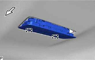
| | Front |
(f) Disconnect the connector to remove the spot light assembly.
Installation
INSTALLATION
PROCEDURE
1. INSTALL SPOT LIGHT ASSEMBLY
(a) Connect the connector.
(b) Engage the 4 clips to install the spot light assembly.
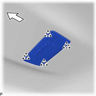
.png) | Front |
 Rear Door Courtesy Switch
ComponentsCOMPONENTS ILLUSTRATION *1 REAR DOOR COURTESY LIGHT SWITCH ASSEMBLY - - N*m (kgf*cm, ft.*lbf): Specified torque - - RemovalREMOVAL CAUTION / NOTICE / HINT HINT:
Us ...
 Scuff Plate Light
ComponentsCOMPONENTS ILLUSTRATION *1 FRONT DOOR SCUFF PLATE LH *2 FRONT DOOR SCUFF PLATE RH RemovalREMOVAL PROCEDURE 1. REMOVE FRONT DOOR SCUFF PLATE LH Click here 2. REMOVE FRONT DO ...
Other materials:
Lexus RX (RX 350L, RX450h) 2016-2026 Repair Manual > Heated Steering Wheel System: Steering Wheel does not Heat Up When Heated Steering Wheel Switch is Pressed
DESCRIPTION Click here WIRING DIAGRAM CAUTION / NOTICE / HINT HINT:
Inspect the fuses for circuits related to this system before performing the following inspection procedure.
The steering wheel heater unit is built into the steering wheel assembly which cannot be disassembled. Therefore, wh ...
Lexus RX (RX 350L, RX450h) 2016-2026 Repair Manual > Vehicle Stability Control System: Left Rear Wheel Speed Sensor Circuit Short to Ground or Open (C050C14)
DESCRIPTION Refer to DTC C050C1F. Click here DTC No. Detection Item DTC Detection Condition Trouble Area C050C14 Left Rear Wheel Speed Sensor Circuit Short to Ground or Open An open in the speed sensor signal circuit continues for 0.5 seconds or more.
Rear speed sensor LH*1
...
Lexus RX (RX 350L, RX450h) 2016-{YEAR} Owners Manual
- For your information
- Pictorial index
- For safety and security
- Instrument cluster
- Operation of each component
- Driving
- Lexus Display Audio system
- Interior features
- Maintenance and care
- When trouble arises
- Vehicle specifications
- For owners
Lexus RX (RX 350L, RX450h) 2016-{YEAR} Repair Manual

0.0105