Lexus RX (RX 350L, RX450h) 2016-2026 Repair Manual: Clock
Components
COMPONENTS
ILLUSTRATION
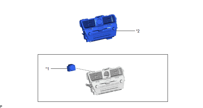
| *1 | CLOCK ASSEMBLY | *2 | RADIO RECEIVER ASSEMBLY WITH REGISTER |
Removal
REMOVAL
CAUTION / NOTICE / HINT
The necessary procedures (adjustment, calibration, initialization or registration) that must be performed after parts are removed and installed, or replaced during clock assembly removal/installation are shown below.
Necessary Procedures After Parts Removed/Installed/Replaced| Replaced Part or Performed Procedure | Necessary Procedure | Effect/Inoperative Function when Necessary Procedure not Performed | Link |
|---|---|---|---|
| Disconnect cable from negative battery terminal | Memorize steering angle neutral point | Lane Control System | |
| Pre-collision system | |||
| Intelligent clearance sonar system*1 | |||
| Parking Assist Monitor System | | ||
| Panoramic View Monitor System | | ||
| Lighting System (w/ Automatic Headlight Beam Level Control System) | | ||
| Initialize back door lock | Power door lock control system | | |
| Reset back door close position | Power Back Door System (w/ Outside Door Control Switch) | |
*1: When performing learning using the Techstream.
Click here .gif)
PROCEDURE
1. REMOVE RADIO RECEIVER ASSEMBLY WITH REGISTER
Click here
2. REMOVE CLOCK ASSEMBLY
(a) Using a screwdriver, disengage the 2 claws and remove the clock assembly as shown in the illustration.
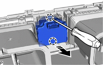
.png) | Remove in this Direction |
Installation
INSTALLATION
PROCEDURE
1. INSTALL CLOCK ASSEMBLY
(a) Engage the 2 claws as shown in the illustration to install the clock assembly.
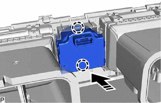
.png) | Install in this Direction |
2. INSTALL RADIO RECEIVER ASSEMBLY WITH REGISTER
Click here .gif)


Other materials:
Lexus RX (RX 350L, RX450h) 2016-2026 Owners Manual > Using the other interior
features: Compass
The compass on the inside rear view mirror indicates the direction in
which
the vehicle is heading.
Operation
To turn the compass on or off, press and
hold the switch for 3 seconds.
Displays and directions
Calibrating the compass
The direction display deviates from the true direction ...
Lexus RX (RX 350L, RX450h) 2016-2026 Repair Manual > Lane Control System: How To Proceed With Troubleshooting
CAUTION / NOTICE / HINT HINT:
Use the following procedure to troubleshoot the lane control system.
*: Use the Techstream.
PROCEDURE 1. VEHICLE BROUGHT TO WORKSHOP
NEXT 2. CUSTOMER PROBLEM ANALYSIS HINT:
In troubleshooting, confirm that the problem sympto ...
Lexus RX (RX 350L, RX450h) 2016-{YEAR} Owners Manual
- For your information
- Pictorial index
- For safety and security
- Instrument cluster
- Operation of each component
- Driving
- Lexus Display Audio system
- Interior features
- Maintenance and care
- When trouble arises
- Vehicle specifications
- For owners
Lexus RX (RX 350L, RX450h) 2016-{YEAR} Repair Manual

0.0104