Lexus RX (RX 350L, RX450h) 2016-2026 Repair Manual: Removal
REMOVAL
CAUTION / NOTICE / HINT
The necessary procedures (adjustment, calibration, initialization or registration) that must be performed after parts are removed and installed, or replaced during combination meter assembly removal/installation are shown below.
Necessary Procedures After Parts Removed/Installed/Replaced| Replaced Part or Performed Procedure | Necessary Procedure | Effect/Inoperative Function when Necessary Procedure not Performed | Link |
|---|---|---|---|
| Disconnect cable from negative battery terminal | Memorize steering angle neutral point | Lane Control System | |
| Pre-collision system | |||
| Intelligent clearance sonar system*1 | |||
| Parking Assist Monitor System | | ||
| Panoramic View Monitor System | | ||
| Lighting System (w/ Automatic Headlight Beam Level Control System) | | ||
| Initialize back door lock | Power door lock control system | | |
| Reset back door close position | Power Back Door System (w/ Outside Door Control Switch) | |
*1: When performing learning using the Techstream.
Click here .gif)
PROCEDURE
1. PRECAUTION
NOTICE:
After turning the engine switch off, waiting time may be required before disconnecting the cable from the negative (-) battery terminal. Therefore, make sure to read the disconnecting the cable from the negative (-) battery terminal notices before proceeding with work.
Click here
2. CHANGE POWER TILT AND POWER TELESCOPIC STEERING COLUMN SYSTEM SETTINGS
Click here
3. DISCONNECT CABLE FROM NEGATIVE BATTERY TERMINAL
NOTICE:
When disconnecting the cable, some systems need to be initialized after the cable is reconnected.
Click here
4. REMOVE INSTRUMENT PANEL GARNISH LH
Click here
5. REMOVE FRONT DOOR SCUFF PLATE LH
Click here
6. REMOVE COWL SIDE TRIM BOARD LH
Click here
7. REMOVE NO. 1 INSTRUMENT PANEL UNDER COVER SUB-ASSEMBLY
Click here
8. DISCONNECT HOOD LOCK CONTROL LEVER SUB-ASSEMBLY
Click here
9. REMOVE LOWER INSTRUMENT PANEL FINISH PANEL SUB-ASSEMBLY
Click here
10. REMOVE LOWER NO. 2 INSTRUMENT PANEL FINISH PANEL
Click here
11. REMOVE LOWER NO. 1 INSTRUMENT PANEL FINISH PANEL
Click here
12. REMOVE INSTRUMENT CLUSTER FINISH PANEL ORNAMENT
Click here
13. REMOVE LOWER INSTRUMENT FINISH PANEL SUB
Click here
14. REMOVE INSTRUMENT CLUSTER FINISH PANEL SUB-ASSEMBLY
| (a) Disengage the 2 claws and 4 clips to separate the instrument cluster finish panel sub-assembly. |
|
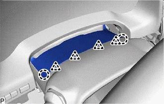
(b) Disengage the 4 clips as shown in the illustration.
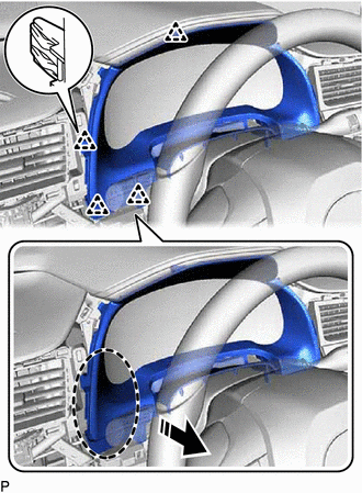
.png) | Place Hand Here |
.png) | Remove in this Direction |
(c) Disengage the 3 clips as shown in the illustration.
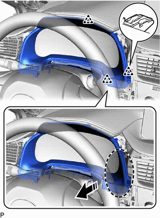
| | Place Hand Here |
| | Remove in this Direction |
(d) Disconnect the connector to remove the instrument cluster finish panel sub-assembly.
15. REMOVE COMBINATION METER ASSEMBLY
| (a) Remove the 4 screws. |
|
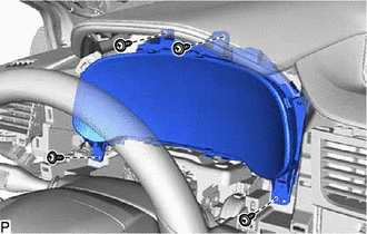
(b) Disengage the clamp.
(c) Disconnect each connector to remove the combination meter assembly.
 Disassembly
DISASSEMBLY PROCEDURE 1. REMOVE COMBINATION METER GLASS (for Optitron Meter Type) (a) Disengage the 8 claws to remove the combination meter glass. 2. REMOVE COMBINATION METER GLASS (for ...
 Reassembly
REASSEMBLY PROCEDURE 1. INSTALL COMBINATION METER GLASS (for Optitron Meter Type) (a) Engage the 8 claws to install the combination meter glass. 2. INSTALL COMBINATION METER GLASS (for ...
Other materials:
Lexus RX (RX 350L, RX450h) 2016-2026 Repair Manual > Rear Door Opening Trim Weatherstrip: Removal
REMOVAL CAUTION / NOTICE / HINT The necessary procedures (adjustment, calibration, initialization or registration) that must be performed after parts are removed and installed, or replaced during rear door opening trim weatherstrip removal/installation are shown below. Necessary Procedures After Par ...
Lexus RX (RX 350L, RX450h) 2016-2026 Repair Manual > Generator (for 180 A Type): Removal
REMOVAL CAUTION / NOTICE / HINT The necessary procedures (adjustment, calibration, initialization or registration) that must be performed after parts are removed and installed, or replaced during generator assembly removal/installation are shown below. Necessary Procedures After Parts Removed/Instal ...
Lexus RX (RX 350L, RX450h) 2016-{YEAR} Owners Manual
- For your information
- Pictorial index
- For safety and security
- Instrument cluster
- Operation of each component
- Driving
- Lexus Display Audio system
- Interior features
- Maintenance and care
- When trouble arises
- Vehicle specifications
- For owners
Lexus RX (RX 350L, RX450h) 2016-{YEAR} Repair Manual

0.0099