Lexus RX (RX 350L, RX450h) 2016-2026 Repair Manual: Open in Turn Signal Circuit (B1507)
DESCRIPTION
These DTCs are stored when the combination meter assembly detects an open in a turn signal light circuit, or a short in a turn signal light circuit or the hazard warning light circuit.
HINT:
- If there is an open in a front turn signal light circuit or rear turn signal light circuit, the turn signal lights on the side with the open circuit will blink faster than usual.
- If there is an open in a side turn signal light circuit, DTC B1507 will not be stored.
| DTC No. | Detection Item | DTC Detection Condition | Trouble Area | Memory | Note |
|---|---|---|---|---|---|
| B1507 | Open in Turn Signal Circuit | Diagnosis Condition:
Malfunction Status:
|
for TMK Made
for TMMC Made
| DTC stored | - |
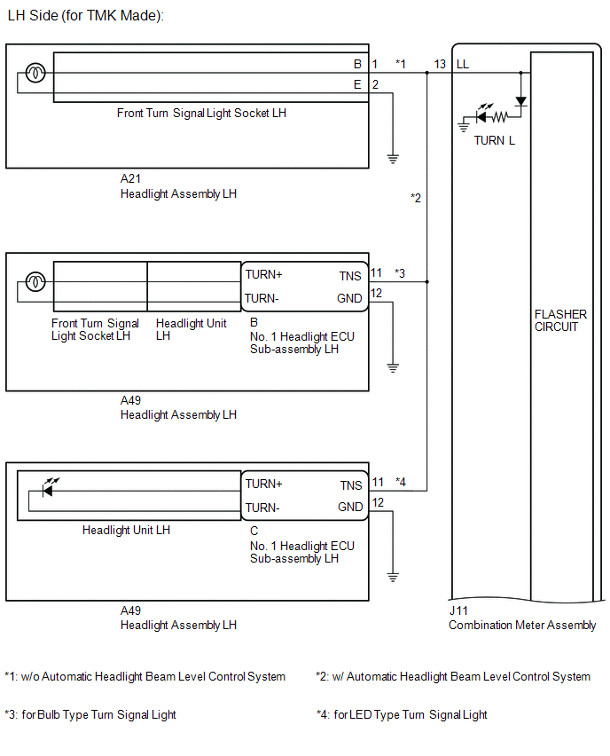
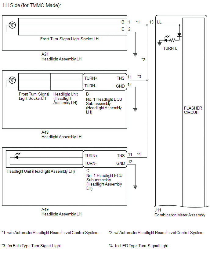
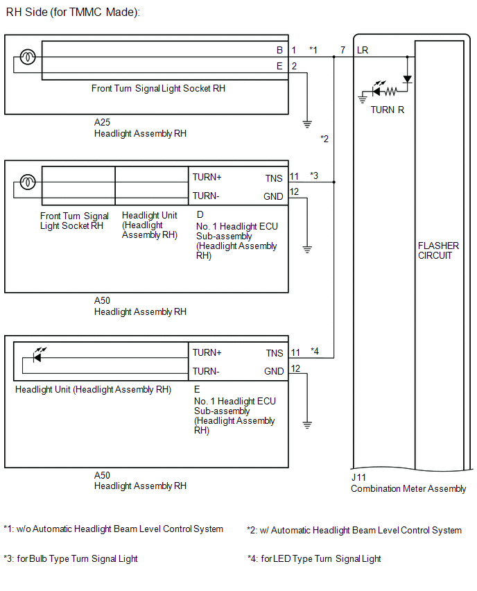
- *1: w/ Automatic Headlight Beam Level Control System
- *2: for Bulb Type Turn Signal Light
- *3: for LED Type Turn Signal Light
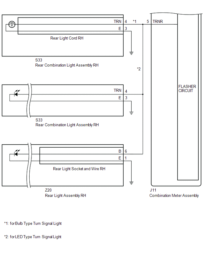
WIRING DIAGRAM


CAUTION / NOTICE / HINT
NOTICE:
- When replacing the combination meter assembly, always replace it with a new one. If a combination meter assembly which was installed to another vehicle is used, the information stored in it will not match the information from the vehicle and a DTC may be stored.
- When replacing the No. 1 headlight ECU sub-assembly LH, always replace it with a new one. If a No. 1 headlight ECU sub-assembly LH which was installed to another vehicle is used, the information stored in it will not match the information from the vehicle and a DTC may be stored.
- Inspect the LEDs and bulbs for this system before performing the following procedure.
PROCEDURE
| 1. | CHECK SYMPTOMS |
(a) Check the problem symptoms.
| Result | Proceed to |
|---|---|
| LH side front turn signal light does not blink | A |
| LH side rear turn signal light (rear combination light assembly side) does not blink | B |
| LH side rear turn signal light (rear light assembly side) does not blink | C |
| LH side rear turn signal light (rear combination light assembly and rear light assembly) does not blink | D |
| RH side front turn signal light does not blink | E |
| RH side rear turn signal light (rear combination light assembly) does not blink | F |
| LH side rear turn signal light (rear light assembly) does not blink | G |
| LH side rear turn signal light (rear combination light assembly and rear light assembly) does not blink | H |
| B | .gif) | GO TO STEP 13 |
| C | | GO TO STEP 15 |
| D | | GO TO STEP 18 |
| E | | GO TO STEP 19 |
| F | | GO TO STEP 30 |
| G | | GO TO STEP 32 |
| H | | GO TO STEP 35 |
|
.gif)
| 2. | CONFIRM MODEL |
| Result | Proceed to |
|---|---|
| w/o Automatic Headlight Beam Level Control System | A |
| w/ Automatic Headlight Beam Level Control System (for Bulb Type Front Turn Signal Light (for TMK Made)) | B |
| w/ Automatic Headlight Beam Level Control System (for Bulb Type Front Turn Signal Light (for TMMC Made)) | C |
| w/ Automatic Headlight Beam Level Control System (for LED Type Front Turn Signal Light (for TMK Made)) | D |
| w/ Automatic Headlight Beam Level Control System (for LED Type Front Turn Signal Light (for TMMC Made)) | E |
| A | | GO TO STEP 7 |
| C | | GO TO STEP 5 |
| D | | GO TO STEP 8 |
| E | | GO TO STEP 10 |
|
| 3. | INSPECT NO. 1 HEADLIGHT ECU SUB-ASSEMBLY LH |
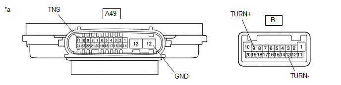
| *a | Component without harness connected (No. 1 Headlight ECU Sub-assembly LH) | - | - |
(a) Remove the No. 1 headlight ECU sub-assembly LH.
Click here .gif)
(b) Measure the resistance according to the value(s) in the table below.
Standard Resistance:
| Tester Connection | Condition | Specified Condition |
|---|---|---|
| A49-11 (TNS) - B-9 (TURN+) | Always | Below 1 Ω |
| A49-12 (GND) - B-13 (TURN-) | Always | Below 1 Ω |
| NG | | REPLACE NO. 1 HEADLIGHT ECU SUB-ASSEMBLY LH |
|
| 4. | CHECK LH SIDE FRONT TURN SIGNAL LIGHT (HEADLIGHT UNIT LH) |
(a) Remove the front turn signal light socket LH.
Click here
(b) Interchange the headlight unit LH with RH and connect the connectors.
Click here
(c) Connect the front turn signal light socket LH connectors.
(d) Connect the No. 1 headlight ECU sub-assembly LH connectors.
(e) Operate the turn signal switch and check that the LH side front turn signal light operates normally.
HINT:
If the LH side front turn signal light operates normally, the headlight unit LH is malfunctioning.
| Result | Proceed to |
|---|---|
| LH side front turn signal light operates normally | A |
| Problem symptoms do not change (LH side front turn signal light does not blink) | B |
| A | | REPLACE HEADLIGHT UNIT LH |
| B | | GO TO STEP 7 |
| 5. | INSPECT NO. 1 HEADLIGHT ECU SUB-ASSEMBLY (HEADLAMP ASSEMBLY LH) |
| *a | Component without harness connected (No. 1 Headlight ECU Sub-assembly (Headlight Assembly LH)) | - | - |
(a) Remove the No. 1 headlight ECU sub-assembly (headlight assembly LH).
Click here
(b) Measure the resistance according to the value(s) in the table below.
Standard Resistance:
| Tester Connection | Condition | Specified Condition |
|---|---|---|
| A49-11 (TNS) - B-9 (TURN+) | Always | Below 1 Ω |
| A49-12 (GND) - B-13 (TURN-) | Always | Below 1 Ω |
| NG | | REPLACE HEADLIGHT ASSEMBLY LH |
|
| 6. | CHECK LH SIDE FRONT TURN SIGNAL LIGHT (HEADLIGHT UNIT (HEADLIGHT ASSEMBLY LH)) |
(a) Remove the front turn signal light socket LH.
Click here
(b) Interchange the headlight unit (headlight assembly LH with RH) and connect the connectors.
Click here
(c) Connect the front turn signal light socket LH connectors.
(d) Connect the No. 1 headlight ECU sub-assembly (headlight assembly LH) connectors.
(e) Operate the turn signal switch and check that the LH side front turn signal light operates normally.
HINT:
If the LH side front turn signal light operates normally, the headlight unit (headlight assembly LH) is malfunctioning.
| Result | Proceed to |
|---|---|
| LH side front turn signal light operates normally | A |
| Problem symptoms do not change (LH side front turn signal light does not blink) | B |
| A | | REPLACE HEADLIGHT ASSEMBLY LH |
|
| 7. | CHECK LH SIDE FRONT TURN SIGNAL LIGHT (Front Turn Signal Light Socket LH) |
(a) Interchange the front turn signal light socket LH with RH and connect the connectors.
Click here
(b) Operate the turn signal switch and check that the LH side front turn signal light operates normally.
HINT:
If the LH side front turn signal light operates normally, the front turn signal light socket LH is malfunctioning.
| Result | Proceed to |
|---|---|
| LH side front turn signal light operates normally | A |
| Problem symptoms do not change (LH side front turn signal light does not blink) | B |
| A | | REPLACE FRONT TURN SIGNAL LIGHT SOCKET LH |
| B | | GO TO STEP 12 |
| 8. | INSPECT NO. 1 HEADLIGHT ECU SUB-ASSEMBLY LH |

| *a | Component without harness connected (No. 1 Headlight ECU Sub-assembly LH) | - | - |
(a) Remove the No. 1 headlight ECU sub-assembly LH.
Click here
(b) Measure the resistance according to the value(s) in the table below.
Standard Resistance:
| Tester Connection | Condition | Specified Condition |
|---|---|---|
| A49-11 (TNS) - B-20 (TURN+) | Always | Below 1 Ω |
| A49-12 (GND) - B-13 (TURN-) | Always | Below 1 Ω |
| NG | | REPLACE NO. 1 HEADLIGHT ECU SUB-ASSEMBLY LH |
|
| 9. | CHECK LH SIDE FRONT TURN SIGNAL LIGHT (HEADLIGHT UNIT LH) |
(a) Interchange the headlight unit LH with RH and connect the connectors.
Click here
(b) Connect the No. 1 headlight ECU sub-assembly LH connectors.
(c) Operate the turn signal switch and check that the LH side front turn signal light operates normally.
HINT:
If the LH side front turn signal light operates normally, the headlight unit LH is malfunctioning.
| Result | Proceed to |
|---|---|
| LH side front turn signal light operates normally | A |
| Problem symptoms do not change (LH side front turn signal light does not blink) | B |
| A | | REPLACE HEADLIGHT UNIT LH |
| B | | GO TO STEP 12 |
| 10. | INSPECT NO. 1 HEADLIGHT ECU SUB-ASSEMBLY (HEADLIGHT ASSEMBLY LH) |
| *a | Component without harness connected (No. 1 Headlight ECU Sub-assembly (Headlight Assembly LH)) | - | - |
(a) Remove the No. 1 headlight ECU sub-assembly (headlight assembly LH).
Click here
(b) Measure the resistance according to the value(s) in the table below.
Standard Resistance:
| Tester Connection | Condition | Specified Condition |
|---|---|---|
| A49-11 (TNS) - B-20 (TURN+) | Always | Below 1 Ω |
| A49-12 (GND) - B-13 (TURN-) | Always | Below 1 Ω |
| NG | | REPLACE HEADLIGHT ASSEMBLY LH |
|
| 11. | CHECK LH SIDE FRONT TURN SIGNAL LIGHT (HEADLIGHT UNIT (HEADLIGHT ASSEMBLY LH)) |
(a) Interchange the headlight unit (headlight assembly LH with RH) and connect the connectors.
Click here
(b) Connect the No. 1 headlight ECU sub-assembly (headlight assembly LH) connectors.
(c) Operate the turn signal switch and check that the LH side front turn signal light operates normally.
HINT:
If the LH side front turn signal light operates normally, the headlight unit (headlight assembly LH) is malfunctioning.
| Result | Proceed to |
|---|---|
| LH side front turn signal light operates normally | A |
| Problem symptoms do not change (LH side front turn signal light does not blink) | B |
| A | | REPLACE HEADLIGHT ASSEMBLY LH |
|
| 12. | CHECK HARNESS AND CONNECTOR (HEADLIGHT ASSEMBLY LH - COMBINATION METER ASSEMBLY AND BODY GROUND) |
(a) Disconnect the A21*1 or A49*2 headlight assembly LH connector.
(b) Disconnect the J11 combination meter assembly connector.
(c) Measure the resistance according to the value(s) in the table below.
Standard Resistance:
| Tester Connection | Condition | Specified Condition |
|---|---|---|
| A21-11(TNS)*1 or A49-11 (TNS)*2 - J11-13 (LL) | Always | Below 1 Ω |
| A21-2 (E) - Body ground*1 | Always | Below 1 Ω |
| A49-12 (GND) - Body ground | Always | Below 1 Ω |
- *1: w/o Automatic Headlight Beam Level Control System
- *2: w/ Automatic Headlight Beam Level Control System
| OK | | REPLACE COMBINATION METER ASSEMBLY |
| NG | | REPAIR OR REPLACE HARNESS OR CONNECTOR |
| 13. | INSPECT REAR COMBINATION LIGHT ASSEMBLY LH |
(a) Remove the rear combination light assembly LH.
w/ Rear No. 2 Seat: Click here
w/o Rear No. 2 Seat: Click here
(b) Inspect the turn signal light in the rear combination light assembly LH.
w/ Rear No. 2 Seat: Click here
w/o Rear No. 2 Seat: Click here
| Result | Proceed to |
|---|---|
| OK | A |
| NG (for Bulb Type Rear Turn Signal Light) | B |
| NG (for LED Type Rear Turn Signal Light) | C |
| B | | REPLACE REAR LIGHT CORD LH |
| C | | REPLACE REAR COMBINATION LIGHT ASSEMBLY LH |
|
| 14. | CHECK HARNESS AND CONNECTOR (REAR COMBINATION LIGHT ASSEMBLY LH - COMBINATION METER ASSEMBLY AND BODY GROUND) |
(a) Disconnect the S31 rear combination light assembly LH connector.
(b) Disconnect the J11 combination meter assembly connector.
(c) Measure the resistance according to the value(s) in the table below.
Standard Resistance:
| Tester Connection | Condition | Specified Condition |
|---|---|---|
| S31-4 (TRN) - J11-11 (TRNL) | Always | Below 1 Ω |
| S31-3 (E) - Body ground | Always | Below 1 Ω |
| OK | | REPLACE COMBINATION METER ASSEMBLY |
| NG | | REPAIR OR REPLACE HARNESS OR CONNECTOR |
| 15. | INSPECT REAR LGHT ASSEMBLY LH |
(a) Remove the rear light assembly LH.
Click here
(b) Inspect the turn signal light in the rear light assembly LH.
Click here
| NG | | GO TO STEP 17 |
|
| 16. | CHECK HARNESS AND CONNECTOR (REAR LIGHT ASSEMBLY LH - COMBINATION METER ASSEMBLY AND BODY GROUND) |
(a) Disconnect the Z21 rear light assembly LH connector.
(b) Disconnect the J11 combination meter assembly connector.
(c) Measure the resistance according to the value(s) in the table below.
Standard Resistance:
| Tester Connection | Condition | Specified Condition |
|---|---|---|
| Z21-6 (B) - J11-11 (TRNL) | Always | Below 1 Ω |
| Z21-1 (E) - Body ground | Always | Below 1 Ω |
| OK | | REPLACE COMBINATION METER ASSEMBLY |
| NG | | REPAIR OR REPLACE HARNESS OR CONNECTOR |
| 17. | CHECK LH SIDE REAR TURN SIGNAL LIGHT (REAR LIGHT SOCKET AND WIRE LH) |
(a) Interchange the rear light socket and wire LH with RH and connect the connectors.
Click here
(b) Operate the turn signal switch and check that the LH side rear turn signal light operates normally.
HINT:
If the LH side rear turn signal light operates normally, the rear light socket and wire LH is malfunctioning.
| Result | Proceed to |
|---|---|
| LH side rear turn signal light operates normally | A |
| Problem symptoms do not change (LH side rear turn signal light does not blink) | B |
| A | | REPLACE REAR LIGHT SOCKET AND WIRE LH |
| B | | REPLACE REAR LIGHT ASSEMBLY LH |
| 18. | CHECK HARNESS AND CONNECTOR (REAR COMBINATION LIGHT ASSEMBLY LH AND REAR LIGHT ASSEMBLY LH - COMBINATION METER ASSEMBLY AND BODY GROUND) |
(a) Disconnect the S31 rear combination light assembly LH connector.
(b) Disconnect the Z21 rear light assembly LH connector.
(c) Disconnect the J11 combination meter assembly connector.
(d) Measure the resistance according to the value(s) in the table below.
Standard Resistance:
| Tester Connection | Condition | Specified Condition |
|---|---|---|
| S31-4 (TRN) - J11-11 (TRNL) | Always | Below 1 Ω |
| Z21-6 (B) - J11-11 (TRNL) | Always | Below 1 Ω |
| S31-3 (E) - Body ground | Always | Below 1 Ω |
| Z21-1 (E) - Body ground | Always | Below 1 Ω |
| OK | | REPLACE COMBINATION METER ASSEMBLY |
| NG | | REPAIR OR REPLACE HARNESS OR CONNECTOR |
| 19. | CONFIRM MODEL |
| Result | Proceed to |
|---|---|
| w/o Automatic Headlight Beam Level Control System | A |
| w/ Automatic Headlight Beam Level Control System (for Bulb Type Front Turn Signal Light (for TMK Made)) | B |
| w/ Automatic Headlight Beam Level Control System (for Bulb Type Front Turn Signal Light (for TMMC Made)) | C |
| w/ Automatic Headlight Beam Level Control System (for LED Type Front Turn Signal Light (for TMK Made)) | D |
| w/ Automatic Headlight Beam Level Control System (for LED Type Front Turn Signal Light (for TMMC Made)) | E |
| A | | GO TO STEP 24 |
| C | | GO TO STEP 22 |
| D | | GO TO STEP 25 |
| E | | GO TO STEP 27 |
|
| 20. | INSPECT NO. 1 HEADLIGHT ECU SUB-ASSEMBLY RH |

| *a | Component without harness connected (No. 1 Headlight ECU Sub-assembly RH) | - | - |
(a) Remove the No. 1 headlight ECU sub-assembly RH.
Click here
(b) Measure the resistance according to the value(s) in the table below.
Standard Resistance:
| Tester Connection | Condition | Specified Condition |
|---|---|---|
| A50-11 (TNS) - D-9 (TURN+) | Always | Below 1 Ω |
| A50-12 (GND) - D-13 (TURN-) | Always | Below 1 Ω |
| NG | | REPLACE NO. 1 HEADLAMP ECU SUB-ASSEMBLY RH |
|
| 21. | CHECK RH SIDE FRONT TURN SIGNAL LIGHT (HEADLIGHT UNIT RH) |
(a) Remove the front turn signal light socket RH.
Click here
(b) Interchange the headlight unit RH with LH and connect the connectors.
Click here
(c) Connect the front turn signal light socket RH connectors.
(d) Connect the No. 1 headlight ECU sub-assembly RH connectors.
(e) Operate the turn signal switch and check that the RH side front turn signal light operates normally.
HINT:
If the RH side front turn signal light operates normally, the headlight unit RH is malfunctioning.
| Result | Proceed to |
|---|---|
| RH side front turn signal light operates normally | A |
| Problem symptoms do not change (RH side front turn signal light does not blink) | B |
| A | | REPLACE HEADLIGHT UNIT RH |
| B | | GO TO STEP 24 |
| 22. | INSPECT HEADLAMP ECU SUB-ASSEMBLY (HEADLIGHTASSEMBLY RH) |
| *a | Component without harness connected (No. 1 Headlight ECU Sub-assembly (Headlight Assembly RH)) | - | - |
(a) Remove the No. 1 headlight ECU sub-assembly (headlight assembly RH).
Click here
(b) Measure the resistance according to the value(s) in the table below.
Standard Resistance:
| Tester Connection | Condition | Specified Condition |
|---|---|---|
| A50-11 (TNS) - D-9 (TURN+) | Always | Below 1 Ω |
| A50-12 (GND) - D-13 (TURN-) | Always | Below 1 Ω |
| NG | | REPLACE HEADLIGHT ASSEMBLY RH |
|
| 23. | CHECK RH SIDE FRONT TURN SIGNAL LIGHT (HEADLIGHT UNIT (HEADLIGHT ASSEMBLY RH)) |
(a) Remove the front turn signal light socket RH.
Click here
(b) Interchange the headlight unit (headlight assembly RH with LH) and connect the connectors.
Click here
(c) Connect the front turn signal light socket RH connectors.
(d) Connect the No. 1 headlight ECU sub-assembly (headlight assembly RH) connectors.
(e) Operate the turn signal switch and check that the RH side front turn signal light operates normally.
HINT:
If the RH side front turn signal light operates normally, the headlight unit (headlight assembly RH) is malfunctioning.
| Result | Proceed to |
|---|---|
| RH side front turn signal light operates normally | A |
| Problem symptoms do not change (RH side front turn signal light does not blink) | B |
| A | | REPLACE HEADLIGHT ASSEMBLY RH |
|
| 24. | CHECK RH SIDE FRONT TURN SIGNAL LIGHT (Front Turn Signal Light Socket RH) |
(a) Interchange the front turn signal light socket RH with LH and connect the connectors.
Click here
(b) Operate the turn signal switch and check that the RH side front turn signal light operates normally.
HINT:
If the RH side front turn signal light operates normally, the front turn signal light socket RH is malfunctioning.
| Result | Proceed to |
|---|---|
| RH side front turn signal light operates normally | A |
| Problem symptoms do not change (RH side front turn signal light does not blink) | B |
| A | | REPLACE FRONT TURN SIGNAL LIGHT SOCKET RH |
| B | | GO TO STEP 29 |
| 25. | INSPECT NO. 1 HEADLIGHT ECU SUB-ASSEMBLY RH |
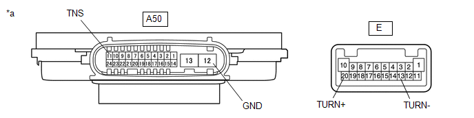
| *a | Component without harness connected (No. 1 Headlight ECU Sub-assembly RH) | - | - |
(a) Remove the No. 1 headlight ECU sub-assembly RH.
Click here
(b) Measure the resistance according to the value(s) in the table below.
Standard Resistance:
| Tester Connection | Condition | Specified Condition |
|---|---|---|
| A50-11 (TNS) - E-20 (TURN+) | Always | Below 1 Ω |
| A50-12 (GND) - E-13 (TURN-) | Always | Below 1 Ω |
| NG | | REPLACE NO. 1 HEADLIGHT ECU SUB-ASSEMBLY RH |
|
| 26. | CHECK RH SIDE FRONT TURN SIGNAL LIGHT (HEADLIGHT UNIT RH) |
(a) Interchange the headlight unit RH with LH and connect the connectors.
Click here
(b) Connect the No. 1 headlight ECU sub-assembly RH connectors.
(c) Operate the turn signal switch and check that the RH side front turn signal light operates normally.
HINT:
If the RH side front turn signal light operates normally, the headlight unit RH is malfunctioning.
| Result | Proceed to |
|---|---|
| RH side front turn signal light operates normally | A |
| Problem symptoms do not change (RH side front turn signal light does not blink) | B |
| A | | REPLACE HEADLIGHT UNIT RH |
| B | | GO TO STEP 29 |
| 27. | INSPECT NO. 1 HEADLIGHT ECU SUB-ASSEMBLY (HEADLIGHT ASSEMBLY RH) |
| *a | Component without harness connected (No. 1 Headlight ECU Sub-assembly (Headlight Assembly RH)) | - | - |
(a) Remove the No. 1 headlight ECU sub-assembly (headlight assembly RH).
Click here
(b) Measure the resistance according to the value(s) in the table below.
Standard Resistance:
| Tester Connection | Condition | Specified Condition |
|---|---|---|
| A50-11 (TNS) - E-20 (TURN+) | Always | Below 1 Ω |
| A50-12 (GND) - E-13 (TURN-) | Always | Below 1 Ω |
| NG | | REPLACE HEADLIGHT ASSEMBLY RH |
|
| 28. | CHECK RH SIDE FRONT TURN SIGNAL LIGHT (HEADLIGHT UNIT (HEADLIGHT ASSEMBLY RH)) |
(a) Interchange the headlight unit (headlight assembly RH with LH) and connect the connectors.
Click here
(b) Connect the No. 1 headlight ECU sub-assembly (headlight assembly RH) connectors.
(c) Operate the turn signal switch and check that the RH side front turn signal light operates normally.
HINT:
If the RH side front turn signal light operates normally, the headlight unit (headlight assembly RH) is malfunctioning.
| Result | Proceed to |
|---|---|
| RH side front turn signal light operates normally | A |
| Problem symptoms do not change (RH side front turn signal light does not blink) | B |
| A | | REPLACE HEADLIGHT ASSEMBLY RH |
|
| 29. | CHECK HARNESS AND CONNECTOR (HEADLIGHT ASSEMBLY RH - COMBINATION METER ASSEMBLY AND BODY GROUND) |
(a) Disconnect the A25*1 or A50*2 headlight assembly RH connector.
(b) Disconnect the J11 combination meter assembly connector.
(c) Measure the resistance according to the value(s) in the table below.
Standard Resistance:
| Tester Connection | Condition | Specified Condition |
|---|---|---|
| A25-11 (TNS)*1 or A50-11 (TNS)*2 - J11-7 (LR) | Always | Below 1 Ω |
| A25-2 (E) - Body ground*2 | Always | Below 1 Ω |
| A50-12 (GND) - Body ground | Always | Below 1 Ω |
- *1: w/o Automatic Headlight Beam Level Control System
- *2: w/ Automatic Headlight Beam Level Control System
| OK | | REPLACE COMBINATION METER ASSEMBLY |
| NG | | REPAIR OR REPLACE HARNESS OR CONNECTOR |
| 30. | INSPECT REAR COMBINATION LIGHT ASSEMBLY RH |
(a) Remove the rear combination light assembly RH.
w/ Rear No. 2 Seat: Click here
w/o Rear No. 2 Seat: Click here
(b) Inspect the turn signal light in the rear combination light assembly RH.
w/ Rear No. 2 Seat: Click here
w/o Rear No. 2 Seat: Click here
| Result | Proceed to |
|---|---|
| OK | A |
| NG (for Bulb Type Rear Turn Signal Light) | B |
| NG (for LED Type Rear Turn Signal Light) | C |
| B | | REPLACE REAR LIGHT CORD RH |
| C | | REPLACE REAR COMBINATION LLIGHT ASSEMBLY RH |
|
| 31. | CHECK HARNESS AND CONNECTOR (REAR COMBINATION LIGHT ASSEMBLY RH - COMBINATION METER ASSEMBLY AND BODY GROUND) |
(a) Disconnect the S33 rear combination light assembly RH connector.
(b) Disconnect the J11 combination meter assembly connector.
(c) Measure the resistance according to the value(s) in the table below.
Standard Resistance:
| Tester Connection | Condition | Specified Condition |
|---|---|---|
| S33-4 (TRN) - J11-5 (TRNR) | Always | Below 1 Ω |
| S33-3 (E) - Body ground | Always | Below 1 Ω |
| OK | | REPLACE COMBINATION METER ASSEMBLY |
| NG | | REPAIR OR REPLACE HARNESS OR CONNECTOR |
| 32. | INSPECT REAR LIGHT ASSEMBLY RH |
(a) Remove the rear light assembly RH.
Click here
(b) Inspect the turn signal light in the rear light assembly RH.
Click here
| NG | | GO TO STEP 34 |
|
| 33. | CHECK HARNESS AND CONNECTOR (REAR LIGHT ASSEMBLY RH - COMBINATION METER ASSEMBLY AND BODY GROUND) |
(a) Disconnect the Z20 rear light assembly RH connector.
(b) Disconnect the J11 combination meter assembly connector.
(c) Measure the resistance according to the value(s) in the table below.
Standard Resistance:
| Tester Connection | Condition | Specified Condition |
|---|---|---|
| Z20-6 (B) - J11-5 (TRNR) | Always | Below 1 Ω |
| Z20-1 (E) - Body ground | Always | Below 1 Ω |
| OK | | REPLACE COMBINATION METER ASSEMBLY |
| NG | | REPAIR OR REPLACE HARNESS OR CONNECTOR |
| 34. | CHECK RH SIDE REAR TURN SIGNAL LIGHT (REAR LIGHT SOCKET AND WIRE RH) |
(a) Interchange the rear light socket and wire RH with LH and connect the connectors.
Click here
(b) Operate the turn signal switch and check that the RH side rear turn signal light operates normally.
HINT:
If the RH side rear turn signal light operates normally, the rear light socket and wire RH is malfunctioning.
| Result | Proceed to |
|---|---|
| RH side rear turn signal light operates normally | A |
| Problem symptoms do not change (RH side rear turn signal light does not blink) | B |
| A | | REPLACE REAR LIGHT SOCKET AND WIRE RH |
| B | | REPLACE REAR LIGHT ASSEMBLY RH |
| 35. | CHECK HARNESS AND CONNECTOR (REAR COMBINATION LIGHT ASSEMBLY RH AND REAR LIGHT ASSEMBLY RH - COMBINATION METER ASSEMBLY AND BODY GROUND) |
(a) Disconnect the S33 rear combination light assembly RH connector.
(b) Disconnect the Z20 rear light assembly RH connector.
(c) Disconnect the J11 combination meter assembly connector.
(d) Measure the resistance according to the value(s) in the table below.
Standard Resistance:
| Tester Connection | Condition | Specified Condition |
|---|---|---|
| S33-4 (TRN) - J11-5 (TRNR) | Always | Below 1 Ω |
| Z20-6 (B) - J11-5 (TRNR) | Always | Below 1 Ω |
| S33-3 (E) - Body ground | Always | Below 1 Ω |
| Z20-1 (E) - Body ground | Always | Below 1 Ω |
| OK | | REPLACE COMBINATION METER ASSEMBLY |
| NG | | REPAIR OR REPLACE HARNESS OR CONNECTOR |
 Fuel Sender Open Detected (B1500)
DESCRIPTION This DTC is stored when the combination meter assembly detects a fuel sender gauge assembly malfunction via a direct line. DTC No. Detection Item DTC Detection Condition Trouble A ...
 Short in Turn Signal / Hazard Flasher Circuit (B1508)
DESCRIPTION This DTC is stored when the combination meter assembly detects a short in a turn signal light circuit. HINT: If there is a short in a turn signal light circuit, all of the turn signal ligh ...
Other materials:
Lexus RX (RX 350L, RX450h) 2016-2026 Repair Manual > Power Mirror Control System (w/o Memory): Customize Parameters
CUSTOMIZE PARAMETERS CUSTOMIZE POWER MIRROR CONTROL SYSTEM (w/o Memory) HINT: The following items can be customized. NOTICE:
When the customer requests a change in a function, first make sure that the function can be customized.
Record the current settings before customizing.
(a) Customizing ...
Lexus RX (RX 350L, RX450h) 2016-2026 Repair Manual > Dynamic Radar Cruise Control System: Cruise Control Input Processor (P160700)
DESCRIPTION When the ECM detects that it is not functioning normally, DTC P160700 is stored. DTC No. Detection Item DTC Detection Condition Trouble Area MIL DTC Output from P160700 Cruise Control Input Processor When the engine switch is on (IG) and control of vehicle speed by t ...
Lexus RX (RX 350L, RX450h) 2016-{YEAR} Owners Manual
- For your information
- Pictorial index
- For safety and security
- Instrument cluster
- Operation of each component
- Driving
- Lexus Display Audio system
- Interior features
- Maintenance and care
- When trouble arises
- Vehicle specifications
- For owners
Lexus RX (RX 350L, RX450h) 2016-{YEAR} Repair Manual

0.0109