Lexus RX (RX 350L, RX450h) 2016-2026 Repair Manual: Fuel Sender Open Detected (B1500)
DESCRIPTION
This DTC is stored when the combination meter assembly detects a fuel sender gauge assembly malfunction via a direct line.
| DTC No. | Detection Item | DTC Detection Condition | Trouble Area | Memory | Note |
|---|---|---|---|---|---|
| B1500 | Fuel Sender Open Detected | When IG voltage is 9.5 V or more and the following condition is detected:
|
| - | - |
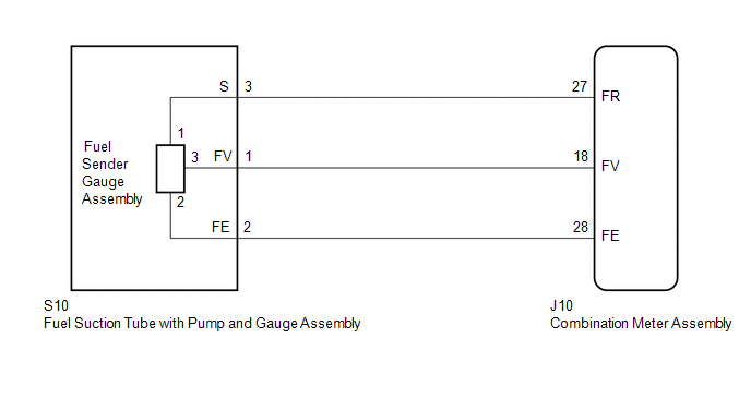
WIRING DIAGRAM
CAUTION / NOTICE / HINT
NOTICE:
When replacing the combination meter assembly, always replace it with a new one. If a combination meter assembly which was installed to another vehicle is used, the information stored in it will not match the information from the vehicle and a DTC may be stored.
PROCEDURE
| 1. | READ VALUE USING TECHSTREAM (FUEL INPUT) |
(a) Connect the Techstream to the DLC3.
(b) Turn the engine switch on (IG).
(c) Turn the Techstream on.
(d) Enter the following menus: Body Electrical / Combination Meter / Data List.
(e) Read the Data List according to the display on the Techstream.
Body Electrical > Combination Meter > Data List| Tester Display | Measurement Item | Range | Normal Condition | Diagnostic Note |
|---|---|---|---|---|
| Fuel Input | Fuel input | Min.: 0 L, Max.: 127.5 L | Fuel receiver gauge indicates F: 64.8 L Fuel receiver gauge indicates 3/4: 54.0 L Fuel receiver gauge indicates 1/2: 36.0 L Fuel receiver gauge indicates 1/4: 18.0 L Fuel receiver gauge indicates E: 7.2 L | Unit: Liter |
| Tester Display |
|---|
| Fuel Input |
| Result | Proceed to |
|---|---|
| Fuel level data can be displayed on the Techstream and DTC B1500 is output. | A |
| Fuel level data cannot be displayed on the Techstream. | B |
| A | .gif) | REPLACE COMBINATION METER ASSEMBLY |
|
.gif)
| 2. | INSPECT FUEL SENDER GAUGE ASSEMBLY (POWER SOURCE) |
| (a) Measure the voltage according to the value(s) in the table below. Standard Voltage:
|
|
| NG | | REPLACE COMBINATION METER ASSEMBLY |
|
| 3. | INSPECT FUEL SENDER GAUGE ASSEMBLY |
| (a) Measure the voltage according to the value(s) in the table below. Standard Voltage:
|
|
| OK | | REPLACE COMBINATION METER ASSEMBLY |
|
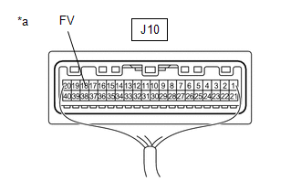
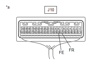
| 4. | CHECK HARNESS AND CONNECTOR (COMBINATION METER ASSEMBLY - FUEL SUCTION TUBE WITH PUMP AND GAUGE ASSEMBLY) |
(a) Disconnect the J10 combination meter assembly connector.
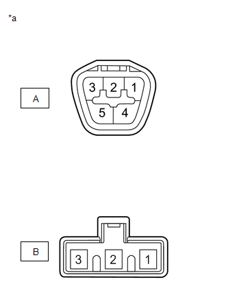
(b) Disconnect the S10 fuel suction tube with pump and gauge assembly connector.
(c) Measure the resistance according to the value(s) in the table below.
Standard Resistance:
| Tester Connection | Condition | Specified Condition |
|---|---|---|
| J10-27 (FR) - S10-3 (S) | Always | Below 1 Ω |
| J10-28 (FE) - S10-2 (FE) | Always | Below 1 Ω |
| J10-18 (FV) - S10-1 (FV) | Always | Below 1 Ω |
| J10-27 (FR) or S10-3 (S) - Body ground | Always | 10 kΩ or higher |
| J10-28 (FE) or S10-2 (FE) - Body ground | Always | 10 kΩ or higher |
| J10-18 (FV) or S10-1 (FV) - Body ground | Always | 10 kΩ or higher |
| NG | | REPAIR OR REPLACE HARNESS OR CONNECTOR |
|
| 5. | INSPECT FUEL SENDER GAUGE ASSEMBLY |
(a) Remove the fuel sender gauge assembly.
Click here .gif)
(b) Inspect the fuel sender gauge assembly.
Click here
OK:
Fuel sender gauge assembly is normal.
| NG | | REPLACE FUEL SENDER GAUGE ASSEMBLY |
|
| 6. | INSPECT FUEL SUCTION TUBE WITH PUMP AND GAUGE ASSEMBLY |
| (a) Measure the resistance according to the value(s) in the table below. Standard Resistance:
|
|
| OK | | REPLACE COMBINATION METER ASSEMBLY |
| NG | | REPLACE FUEL SUCTION TUBE WITH PUMP AND GAUGE ASSEMBLY |
 Lost Communication with Clock Device (Local-CAN) (B1326)
DESCRIPTION After the combination meter assembly has started, the combination meter assembly attempts to detect the clock assembly by performing communication via local bus. This DTC is stored when th ...
 Open in Turn Signal Circuit (B1507)
DESCRIPTION These DTCs are stored when the combination meter assembly detects an open in a turn signal light circuit, or a short in a turn signal light circuit or the hazard warning light circuit. HI ...
Other materials:
Lexus RX (RX 350L, RX450h) 2016-2026 Repair Manual > Can Communication System: Yaw Rate Sensor Communication Stop Mode
DESCRIPTION Detection Item Symptom Trouble Area Yaw Rate Sensor Communication Stop Mode Either condition is met:
"Yaw Rate Sensor" is not displayed on the CAN Bus Check screen of the Techstream.
Click here
Communication system DTCs (DTCs that start with U) that correspond to " ...
Lexus RX (RX 350L, RX450h) 2016-2026 Repair Manual > Engine: On-vehicle Inspection
ON-VEHICLE INSPECTION CAUTION / NOTICE / HINT CAUTION: To prevent injury due to contact with an operating V-ribbed belt or cooling fan, keep your hands and clothing away from the V-ribbed belt and cooling fans when working in the engine compartment with the engine running or the engine switch on (I ...
Lexus RX (RX 350L, RX450h) 2016-{YEAR} Owners Manual
- For your information
- Pictorial index
- For safety and security
- Instrument cluster
- Operation of each component
- Driving
- Lexus Display Audio system
- Interior features
- Maintenance and care
- When trouble arises
- Vehicle specifications
- For owners
Lexus RX (RX 350L, RX450h) 2016-{YEAR} Repair Manual

0.0095