Lexus RX (RX 350L, RX450h) 2016-2026 Repair Manual: Removal
REMOVAL
CAUTION / NOTICE / HINT
The necessary procedures (adjustment, calibration, initialization, or registration) that must be performed after parts are removed and installed, or replaced during rear differential carrier assembly with differential support removal/installation are shown below.
Necessary Procedures After Parts Removed/Installed/Replaced| Replaced Part or Performed Procedure | Necessary Procedure | Effect/Inoperative Function when Necessary Procedure not Performed | Link |
|---|---|---|---|
| Rear wheel alignment adjustment | Calibration |
| |
| Suspension, tires, etc. (The vehicle height changes because of suspension or tire replacement) |
|
| |
| Rear television camera assembly optical axis (Back camera position setting) | Parking assist monitor system | for Initialization: for Calibration: | |
| Panoramic view monitor system | for Initialization: for Calibration: | |
| Initialize No. 1 headlight ECU sub-assembly LH | Lighting System (w/ Automatic Headlight Beam Level Control System) | | |
| Gas leaks from exhaust system | Inspection after repair |
| |
CAUTION:
The rear differential carrier assembly with differential support is very heavy. Be sure to follow the procedure described in the repair manual, or the engine lifter may suddenly drop.
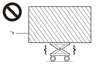
| *a | Object Exceeding Weight Limit of Engine Lifter |
PROCEDURE
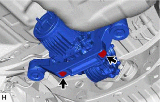
1. DRAIN DIFFERENTIAL OIL
| (a) Using a 10 mm hexagon wrench, remove the differential inspection plug and gasket. |
|
.png)
| (b) Using a 10 mm hexagon wrench, remove the rear differential drain plug and gasket to drain the differential oil. |
|
.png)
2. REMOVE PROPELLER WITH CENTER BEARING SHAFT ASSEMBLY
Click here .gif)
3. REMOVE REAR DRIVE SHAFT ASSEMBLY
(a) Remove the rear drive shaft assembly LH and RH.
Click here
4. REMOVE REAR STABILIZER BAR
w/o Rear No. 2 Seat: Click here
w/ Rear No. 2 Seat: Click here
5. LOOSEN NO. 2 REAR DIFFERENTIAL SUPPORT
HINT:
Loosen the bolts only when removal of the No. 2 rear differential support is required.
| (a) Loosen the 2 bolts. |
|
6. REMOVE REAR DIFFERENTIAL CARRIER ASSEMBLY WITH DIFFERENTIAL SUPPORT
NOTICE:
- Do not damage the contact surface when removing the rear differential carrier assembly with differential support.
- The remaining oil may leak out when removing the rear differential carrier assembly with differential support.
- Securely support the rear differential carrier assembly with differential support while performing this step to avoid excessively tilting or dropping the rear differential carrier assembly with differential support.
- Remove the bolts and nuts with the rear differential carrier assembly with differential support secured.
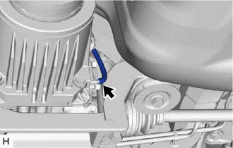
| (a) Disconnect the vacuum hose from the electro magnetic control coupling sub-assembly. |
|
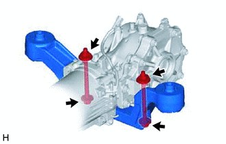
| (b) Support the rear differential carrier assembly with differential support with an engine lifter using 3 attachments or equivalent tools as shown in the illustration. |
|
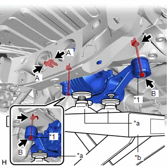
(c) Remove the 2 bolts (A).
(d) Remove the 2 bolts (B), 2 nuts and 2 lower rear differential mount stoppers from the No. 2 rear differential support.
HINT:
The nuts have tabs to prevent them from rotating.
| (e) Disconnect the connector and disengage the clamp (A). |
|
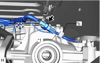
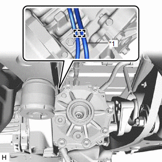
(f) Separate the vacuum hose from the clamp (B).
| (g) Slightly lower the rear differential carrier assembly with differential support, remove the vacuum hose from the clamp. NOTICE: Do not damage the vacuum hose and electro magnetic control coupling wire harness. HINT: Lower the engine lifter to the extent that the vacuum hose can still be removed. |
|
(h) Lower the rear differential carrier assembly with differential support slowly to remove the rear differential carrier assembly with differential support.
NOTICE:
- Do not damage the vacuum hose and electro magnetic control coupling wire harness.
- Move the engine lifter forward and backward as necessary to prevent the rear differential carrier assembly with differential support from contacting the rear suspension member sub-assembly.
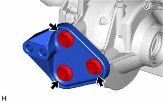
7. REMOVE DIFFERENTIAL SUPPORT
| (a) Remove the 3 bolts and differential support from the rear differential carrier assembly. |
|
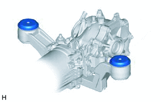
8. REMOVE UPPER REAR DIFFERENTIAL MOUNT STOPPER
| (a) Remove the 2 upper rear differential mount stoppers from the No. 2 rear differential support. |
|
9. REMOVE NO. 2 REAR DIFFERENTIAL SUPPORT
| (a) Remove the 2 bolts, 2 nuts and No. 2 rear differential support. HINT: The nuts have tabs to prevent them from rotating. |
|
 Components
COMPONENTS ILLUSTRATION *1 REAR DIFFERENTIAL DRAIN PLUG *2 DIFFERENTIAL INSPECTION PLUG *3 GASKET - - Tightening torque for "Major areas involving basic vehicle performance ...
 Disassembly
DISASSEMBLY CAUTION / NOTICE / HINT NOTICE:
Before installation, thoroughly clean and dry each part and then apply Toyota Genuine Differential gear oil LT SAE 75W-85 GL-5 or equivalent to them.
D ...
Other materials:
Lexus RX (RX 350L, RX450h) 2016-2026 Repair Manual > Immobiliser System: Engine Immobiliser System Incorrect Assembly (B279C95)
DESCRIPTION If an ECM that is incompatible with the immobiliser system is installed, the ECM will store this DTC. DTC No. Detection Item DTC Detection Condition Trouble Area Note B279C95 Engine Immobiliser System Incorrect Assembly An ECM that is incompatible with the immobiliser ...
Lexus RX (RX 350L, RX450h) 2016-2026 Repair Manual > Pre-collision System: Parts Location
PARTS LOCATION ILLUSTRATION *1 FORWARD RECOGNITION CAMERA *2 MILLIMETER WAVE RADAR SENSOR ASSEMBLY *3 BRAKE ACTUATOR ASSEMBLY - SKID CONTROL ECU *4 ECM ILLUSTRATION *A w/o VDIM *B w/ VDIM *1 AIRBAG SENSOR ASSEMBLY - YAW RATE SENSOR *2 YAW RATE SENSOR ASSEMB ...
Lexus RX (RX 350L, RX450h) 2016-{YEAR} Owners Manual
- For your information
- Pictorial index
- For safety and security
- Instrument cluster
- Operation of each component
- Driving
- Lexus Display Audio system
- Interior features
- Maintenance and care
- When trouble arises
- Vehicle specifications
- For owners
Lexus RX (RX 350L, RX450h) 2016-{YEAR} Repair Manual

0.0123