Lexus RX (RX 350L, RX450h) 2016-2026 Repair Manual: Steering Angle Sensor Module Signal Stuck In Range (C05262A)
DESCRIPTION
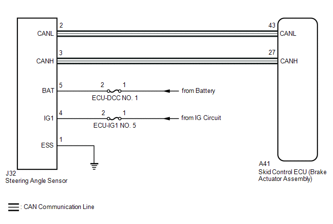
The skid control ECU (brake actuator assembly) receives signals from the steering angle sensor via CAN communication.
HINT:
When a malfunction occurs in the communication line to the steering angle sensor, U012687 is output.
If a DTC related to the CAN communication line is output, first troubleshoot the CAN communication line.
| DTC No. | Detection Item | DTC Detection Condition | Trouble Area |
|---|---|---|---|
| C05262A | Steering Angle Sensor Module Signal Stuck In Range | Normal communication between the skid control ECU and the steering angle sensor and abnormal steering angle sensor zero point. |
|
WIRING DIAGRAM
CAUTION / NOTICE / HINT
NOTICE:
Inspect the fuses for circuits related to this system before performing the following procedure.
PROCEDURE
| 1. | CLEAR DTC |
(a) Connect the Techstream to the DLC3.
(b) Turn the engine switch on (IG).
(c) Operate the Techstream to clear the codes. Enter the following menus: Chassis / Brake/EPB / Trouble Codes.
Chassis > Brake/EPB > Clear DTCs(d) Press the DTC clear button.
(e) Turn the engine switch off.
|
.gif)
| 2. | RECONFIRM DTC |
(a) Turn the engine switch on (IG) and check that no CAN communication system DTCs are output.
HINT:
Click here .gif)
(b) Start the engine.
(c) Drive the vehicle at a speed of 35 km/h (22 mph) and turn the steering wheel to the right and left.
(d) Read the DTCs following the prompts on the Techstream. Enter the following menus: Chassis / Brake/EPB / Trouble Codes.
Chassis > Brake/EPB > Trouble Codes(e) Check that no speed sensor or yaw rate sensor (yaw rate and acceleration sensor) DTCs are output.
| Result | Proceed to |
|---|---|
| DTC C05262A is output. | A |
| CAN communication system DTCs are output. | B |
| Speed sensor and/or yaw rate sensor (yaw rate and acceleration sensor) DTCs are output. | C |
HINT:
- If a speed sensor, or the yaw rate sensor (yaw rate and acceleration sensor) is malfunctioning, DTCs for the steering angle sensor may be stored even though the steering angle sensor is normal.
- If speed sensor and yaw rate sensor (yaw rate and acceleration sensor) DTCs are output simultaneously, repair these malfunctions and then inspect the steering angle sensor.
| B | .gif) | INSPECT CAN COMMUNICATION SYSTEM |
| C | | REPAIR CIRCUITS INDICATED BY OUTPUT DTCS |
|
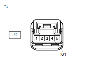
| 3. | CHECK HARNESS AND CONNECTOR (IG1 TERMINAL) |
| (a) Turn the engine switch off. |
|
(b) Make sure that there is no looseness at the locking part and the connecting part of the connectors.
OK:
The connector is securely connected.
(c) Disconnect the J32 steering angle sensor connector.
(d) Check both the connector case and the terminals for deformation and corrosion.
OK:
No deformation or corrosion.
(e) Turn the engine switch on (IG).
(f) Measure the voltage according to the value(s) in the table below.
Standard Voltage:
| Tester Connection | Condition | Specified Condition |
|---|---|---|
| J32-4 (IG1) - Body ground | Engine switch on (IG) | 11 to 14 V |
| NG | | REPAIR OR REPLACE HARNESS OR CONNECTOR |
|
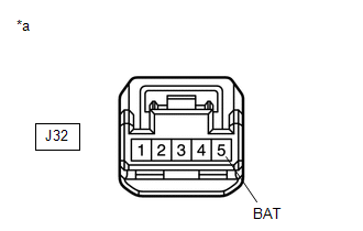
| 4. | CHECK HARNESS AND CONNECTOR (BAT TERMINAL) |
| (a) Turn the engine switch off. |
|
(b) Measure the voltage according to the value(s) in the table below.
Standard Voltage:
| Tester Connection | Condition | Specified Condition |
|---|---|---|
| J32-5 (BAT) - Body ground | Always | 11 to 14 V |
| NG | | REPAIR OR REPLACE HARNESS OR CONNECTOR |
|
| 5. | CHECK HARNESS AND CONNECTOR (GROUND TERMINAL) |
(a) Measure the resistance according to the value(s) in the table below.
Standard Resistance:
| Tester Connection | Condition | Specified Condition |
|---|---|---|
| J32-1 (ESS) - Body ground | 1 minute or more after disconnecting the cable from the negative (-) battery terminal | Below 1 Ω |
| OK | | REPLACE STEERING ANGLE SENSOR |
| NG | | REPAIR OR REPLACE HARNESS OR CONNECTOR |
 Multi-axis Acceleration Sensor Module "A" Signal Compare Failure (C052062)
DESCRIPTION The yaw rate and acceleration sensor has a built-in acceleration sensor and detects the vehicle condition. The skid control ECU (brake actuator assembly) receives signals from the accelera ...
 Steering Angle Sensor Module Component Internal Failure (C052696)
DESCRIPTION The skid control ECU (brake actuator assembly) outputs this DTC when it receives an internal malfunction signal from the steering angle sensor. DTC No. Detection Item DTC Detection ...
Other materials:
Lexus RX (RX 350L, RX450h) 2016-2026 Repair Manual > Occupant Classification System: Diagnosis System
DIAGNOSIS SYSTEM CHECK DLC3 (a) Check the DLC3. Click here FUNCTION OF PASSENGER AIRBAG ON/OFF INDICATOR (a) Initial check (1) Turn the engine switch on (IG). (2) The passenger airbag ON/OFF indicator comes on for approximately 4 seconds, then goes off for approximately 2 seconds. (3) Approximatel ...
Lexus RX (RX 350L, RX450h) 2016-2026 Repair Manual > Lexus Enform System: Does not Recognize Voice Commands Performed to Contact Support Center
PROCEDURE 1. CHECK COMMUNICATION BASED VOICE RECOGNITION FUNCTION (a) While paying attention to the condition of the spoken voice command, say "Find a gas station in New York" and check that voice recognition is operating normally. HINT:
When the voice command is recognized, the content ...
Lexus RX (RX 350L, RX450h) 2016-{YEAR} Owners Manual
- For your information
- Pictorial index
- For safety and security
- Instrument cluster
- Operation of each component
- Driving
- Lexus Display Audio system
- Interior features
- Maintenance and care
- When trouble arises
- Vehicle specifications
- For owners
Lexus RX (RX 350L, RX450h) 2016-{YEAR} Repair Manual

0.0097