Lexus RX (RX 350L, RX450h) 2016-2026 Repair Manual: Removal
REMOVAL
CAUTION / NOTICE / HINT
The necessary procedures (adjustment, calibration, initialization, or registration) that must be performed after parts are removed, installed, or replaced during the spiral cable sub-assembly removal/installation are shown below.
Necessary Procedure After Parts Removed/Installed/Replaced| Replacement Part or Procedure | Necessary Procedures | Effects / Inoperative when not performed | Link |
|---|---|---|---|
| Removal/installation of the spiral cable with sensor sub-assembly |
| Parking assist monitor system | |
| Steering angle neutral point (Initialize panoramic view monitor system) | Panoramic view monitor system | | |
| Steering angle neutral point (Initialize intelligent clearance sonar system) |
| | |
| Disconnect cable from negative battery terminal | Memorize steering angle neutral point | Lane control system | |
| Pre-collision system | |||
| Intelligent clearance sonar system*1 | |||
| Lighting system (w/ Automatic Headlight Beam Level Control System) | | ||
| Parking assist monitor system | | ||
| Panoramic view monitor system | | ||
| Initialize back door lock | Power door lock control system | | |
| Reset back door close position | Power back door system | |
*1: When performing learning using the Techstream.
Click here .gif)
PROCEDURE
1. CHANGE POWER TILT AND POWER TELESCOPIC STEERING COLUMN SYSTEM SETTINGS
Click here
2. REMOVE STEERING WHEEL ASSEMBLY
Click here
3. ALIGN FRONT WHEELS FACING STRAIGHT AHEAD
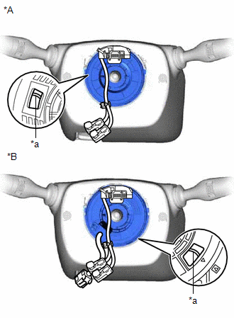
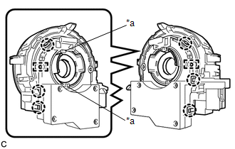
4. INSPECT SPIRAL CABLE WITH SENSOR SUB-ASSEMBLY
| (a) Check the flat cable shown in the illustration. If the flat cable shown in the illustration is not visible, it is possible that the spiral cable with sensor sub-assembly is broken. Replace the spiral cable with sensor sub-assembly with a new one. |
|
5. REMOVE LOWER STEERING COLUMN COVER
Click here
6. REMOVE UPPER STEERING COLUMN COVER
Click here
7. REMOVE SPIRAL CABLE WITH SENSOR SUB-ASSEMBLY
NOTICE:
- Do not replace the spiral cable with sensor sub-assembly with the battery connected and the engine switch on (IG).
- Do not rotate the spiral cable with sensor sub-assembly without the steering wheel assembly installed, with the battery connected and the engine switch on (IG).
- Ensure that the steering wheel assembly is installed and aligned straight when inspecting the steering sensor.
(a) Check that the engine switch is off.
(b) Check that the cable is disconnected from the negative (-) battery terminal.
CAUTION:
Wait at least 90 seconds after disconnecting the cable from the negative (-) battery terminal to disable the SRS system.
.png)
(c) Check that the front wheels are aligned facing straight ahead.
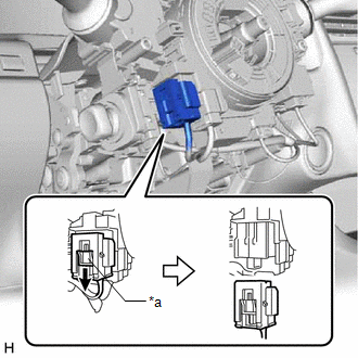
| (d) Slide the slider to release the lock, and then disconnect the yellow airbag connector from the spiral cable with sensor sub-assembly. NOTICE: When disconnecting any airbag connector, take care not to damage the airbag wire harness. |
|
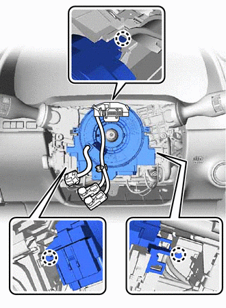
(e) Disconnect the other connectors from the spiral cable with sensor sub-assembly.
| (f) Disengage the 3 claws to remove the spiral cable with sensor sub-assembly. |
|
8. REMOVE SPIRAL CABLE SUB-ASSEMBLY
NOTICE:
- Remove the steering sensor from the spiral cable sub-assembly only when replacing the spiral cable sub-assembly or the steering sensor.
- Removing the steering sensor from the spiral cable sub-assembly without using a lock pin may result in the center position of the steering sensor becoming misaligned. Therefore, make sure to use the lock pin provided with a new spiral cable sub-assembly when removing the steering sensor from the spiral cable sub-assembly.
-
When replacing the steering sensor:
Click here
| (a) Install the lock pin to the steering sensor. NOTICE:
|
|
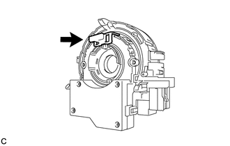
| (b) Disengage the 6 claws and 2 pins, and remove the spiral cable sub-assembly from the steering sensor. NOTICE: Do not damage the pins of the spiral cable sub-assembly or guides of the steering sensor. |
|
 Components
COMPONENTS ILLUSTRATION *A w/o Heated Steering Wheel System and Pre-collision System *B w/ Heated Steering Wheel System or Pre-collision System *1 LOWER STEERING COLUMN COVER *2 SP ...
 Inspection
INSPECTION PROCEDURE 1. INSPECT SPIRAL CABLE SUB-ASSEMBLY NOTICE:
Do not remove the steering sensor from the spiral cable sub-assembly when inspecting the spiral cable sub-assembly.
Remove the st ...
Other materials:
Lexus RX (RX 350L, RX450h) 2016-2026 Repair Manual > Noise Filter (w/ Rear No. 2 Seat): Components
COMPONENTS ILLUSTRATION *1 COOLER (NO. 2 ROOM TEMP. SENSOR) THERMISTOR *2 DECK TRIM SIDE PANEL ASSEMBLY LH *3 FRONT DECK SIDE TRIM COVER LH *4 NO. 1 LUGGAGE COMPARTMENT LIGHT ASSEMBLY *5 NO. 1 LUGGAGE COMPARTMENT TRIM HOOK *6 NO. 2 AIR CONDITIONING CONTROL ASSEMBLY ...
Lexus RX (RX 350L, RX450h) 2016-2026 Repair Manual > Automatic Transaxle System: Definition Of Terms
DEFINITION OF TERMS Term Definition Monitor description Description of what the ECM monitors and how it detects malfunctions (monitoring purpose and details). Related DTCs Group of diagnostic trouble codes that are output by the ECM based on the same malfunction detection logic. ...
Lexus RX (RX 350L, RX450h) 2016-{YEAR} Owners Manual
- For your information
- Pictorial index
- For safety and security
- Instrument cluster
- Operation of each component
- Driving
- Lexus Display Audio system
- Interior features
- Maintenance and care
- When trouble arises
- Vehicle specifications
- For owners
Lexus RX (RX 350L, RX450h) 2016-{YEAR} Repair Manual

0.0102