Lexus RX (RX 350L, RX450h) 2016-2026 Repair Manual: Lost Communication with Clock Device (Local-CAN) (B1326)
DESCRIPTION
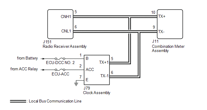
After the combination meter assembly has started, the combination meter assembly attempts to detect the clock assembly by performing communication via local bus.
This DTC is stored when the clock assembly has been detected but communication between the combination meter assembly and clock assembly is interrupted.
| DTC No. | Detection Item | DTC Detection Condition | Trouble Area | Memory | Note |
|---|---|---|---|---|---|
| B1326 | Lost Communication with Clock Device (Local-CAN) | Diagnosis Condition:
Malfunction Status:
Malfunction Time:
|
| DTC stored | - |
WIRING DIAGRAM
CAUTION / NOTICE / HINT
NOTICE:
When replacing the combination meter assembly, always replace it with a new one. If a combination meter assembly which was installed to another vehicle is used, the information stored in it will not match the information from the vehicle and a DTC may be stored.
PROCEDURE
| 1. | CHECK CLOCK ASSEMBLY |
(a) Check the operation of the clock assembly.
| Result | Proceed to |
|---|---|
| The clock assembly is operating correctly | A |
| The clock assembly is not operating correctly | B |
| B | .gif) | GO TO STEP 4 |
|
.gif)
| 2. | CHECK HARNESS AND CONNECTOR (POWER SOURCE - CLOCK ASSEMBLY) |
(a) Disconnect the J79 clock assembly connector.
(b) Measure the voltage according to the value(s) in the table below.
Standard Voltage:
| Tester Connection | Condition | Specified Condition |
|---|---|---|
| J79-1 (B) - Body ground | Engine switch off | 11 to 14 V |
| J79-2 (ACC) - Body ground | Engine switch on (ACC) | 11 to 14 V |
| NG | | REPAIR OR REPLACE HARNESS OR CONNECTOR |
|
| 3. | CHECK HARNESS AND CONNECTOR (CLOCK ASSEMBLY - BODY GROUND) |
(a) Measure the resistance according to the value(s) in the table below.
Standard Resistance:
| Tester Connection | Condition | Specified Condition |
|---|---|---|
| J79-7 (E) - Body ground | Always | Below 1 Ω |
| OK | | REPLACE CLOCK ASSEMBLY |
| NG | | REPAIR OR REPLACE HARNESS OR CONNECTOR |
| 4. | CONFIRM MODEL |
(a) Choose the model to be inspected.
| Result | Proceed to |
|---|---|
| w/o Navigation System | A |
| w/ Navigation System | B |
| B | | GO TO STEP 7 |
|
| 5. | CHECK FOR DTC (AUDIO AND VISUAL SYSTEM) |
(a) Check if audio and visual system DTCs are output.
Body Electrical > Navigation System > Trouble Codes| Result | Proceed to |
|---|---|
| DTCs are not output | A |
| DTCs are output | B |
| B | | GO TO AUDIO AND VISUAL SYSTEM |
|
| 6. | CHECK FOR DTC (AUDIO AND VISUAL SYSTEM) |
(a) Disconnect the J79 clock assembly connector.
(b) Check if audio and visual system DTCs are output.
Body Electrical > Navigation System > Trouble CodesHINT:
When the J79 connector of the clock assembly is disconnected and audio and visual system DTCs are output, if the radio receiver assembly detects the malfunction but the combination meter assembly does not, it can be suspected that the combination meter assembly is malfunctioning.
| Result | Proceed to |
|---|---|
| DTCs are not output | A |
| DTCs are output | B |
| A | | REPLACE RADIO RECEIVER ASSEMBLY |
| B | | REPLACE COMBINATION METER ASSEMBLY |
| 7. | CHECK FOR DTC (NAVIGATION SYSTEM) |
(a) Check if navigation system DTCs are output.
Body Electrical > Navigation System > Trouble Codes| Result | Proceed to |
|---|---|
| DTCs are not output | A |
| DTCs are output | B |
| B | | GO TO NAVIGATION SYSTEM |
|
| 8. | CHECK FOR DTC (NAVIGATION SYSTEM) |
(a) Disconnect the J79 clock assembly connector.
(b) Check if navigation system DTCs are output.
Body Electrical > Navigation System > Trouble CodesHINT:
When the J79 connector of the clock assembly is disconnected and navigation system DTCs are output, if the radio receiver assembly detects the malfunction but the combination meter assembly does not, it can be suspected that the combination meter assembly is malfunctioning.
| Result | Proceed to |
|---|---|
| DTCs are not output | A |
| DTCs are output | B |
| A | | REPLACE RADIO RECEIVER ASSEMBLY |
| B | | REPLACE COMBINATION METER ASSEMBLY |
 Lost Communication with EMV (B1321)
DESCRIPTION After the combination meter assembly has started, the combination meter assembly attempts to detect the radio receiver assembly by performing communication via local bus. This DTC is store ...
 Fuel Sender Open Detected (B1500)
DESCRIPTION This DTC is stored when the combination meter assembly detects a fuel sender gauge assembly malfunction via a direct line. DTC No. Detection Item DTC Detection Condition Trouble A ...
Other materials:
Lexus RX (RX 350L, RX450h) 2016-2026 Repair Manual > Lighting System: Customize Parameters
CUSTOMIZE PARAMETERS PROCEDURE 1. CUSTOMIZE LIGHTING SYSTEM (INT) (a) Customizing using the Techstream HINT: The following items can be customized. NOTICE:
When the customer requests a change in a function, first make sure that the function can be customized.
Be sure to make a note of the curre ...
Lexus RX (RX 350L, RX450h) 2016-2026 Repair Manual > Audio And Visual System (for 12.3 Inch Display): Display does not Dim when Light Control Switch is Turned ON
DESCRIPTION When the audio and visual system is activated with the light control switch in the tail or head position, before AVC-LAN communication is established, the multi-display assembly dims the display according to the illumination signal received via a direct line. After AVC-LAN communication ...
Lexus RX (RX 350L, RX450h) 2016-{YEAR} Owners Manual
- For your information
- Pictorial index
- For safety and security
- Instrument cluster
- Operation of each component
- Driving
- Lexus Display Audio system
- Interior features
- Maintenance and care
- When trouble arises
- Vehicle specifications
- For owners
Lexus RX (RX 350L, RX450h) 2016-{YEAR} Repair Manual

0.0121