Lexus RX (RX 350L, RX450h) 2016-2026 Repair Manual: Lost Communication with EMV (B1321)
DESCRIPTION
After the combination meter assembly has started, the combination meter assembly attempts to detect the radio receiver assembly by performing communication via local bus.
This DTC is stored when the radio receiver assembly has been detected but communication between the combination meter assembly and radio receiver assembly is interrupted.
| DTC No. | Detection Item | DTC Detection Condition | Trouble Area | Memory | Note |
|---|---|---|---|---|---|
| B1321 | Lost Communication with EMV | Diagnosis Condition:
Malfunction Status:
Malfunction Time:
|
| DTC stored | - |
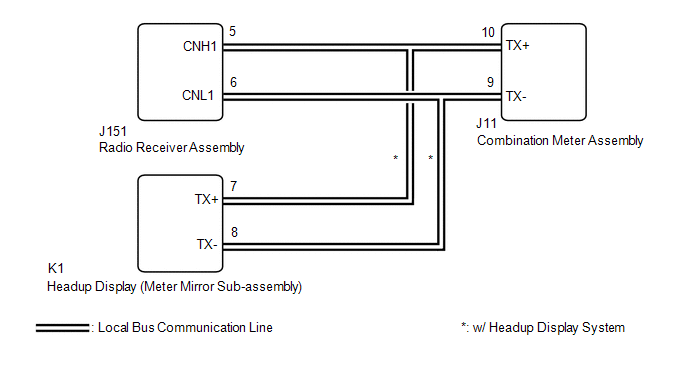
WIRING DIAGRAM
CAUTION / NOTICE / HINT
NOTICE:
When replacing the combination meter assembly, always replace it with a new one. If a combination meter assembly which was installed to another vehicle is used, the information stored in it will not match the information from the vehicle and a DTC may be stored.
PROCEDURE
| 1. | CONFIRM MODEL |
(a) Choose the model to be inspected.
| Result | Proceed to |
|---|---|
| w/o Navigation System | A |
| w/ Navigation System | B |
| B | .gif) | GO TO STEP 3 |
|
.gif)
| 2. | CHECK FOR DTC (AUDIO AND VISUAL SYSTEM) |
(a) Check if audio and visual system DTCs are output.
Body Electrical > Navigation System > Trouble Codes| Result | Proceed to |
|---|---|
| DTCs are not output | A |
| DTCs are output | B |
| A | | GO TO STEP 4 |
| B | | GO TO AUDIO AND VISUAL SYSTEM |
| 3. | CHECK FOR DTC (NAVIGATION SYSTEM) |
(a) Check if navigation system DTCs are output.
Body Electrical > Navigation System > Trouble Codes| Result | Proceed to |
|---|---|
| DTCs are not output | A |
| DTCs are output | B |
| B | | GO TO NAVIGATION SYSTEM |
|
| 4. | CONFIRM MODEL |
(a) Choose the model to be inspected.
| Result | Proceed to |
|---|---|
| w/ Headup Display System | A |
| w/o Headup Display System | B |
| B | | GO TO STEP 6 |
|
| 5. | CHECK FOR DTC (HEADUP DISPLAY SYSTEM) |
(a) Check if headup display system DTCs are output.
Body Electrical > Head Up Display > Trouble CodesHINT:
- If DTC B1321 is output from the meter / gauge system and is not output from the headup display system, it can be suspected that the combination meter assembly has an internal malfunction.
- If DTC B1321 is output from the headup display system and is not output from the audio and visual system or navigation system, it can be suspected that the radio receiver assembly has an internal malfunction.
| Result | Proceed to |
|---|---|
| DTC B1321 is not output | A |
| DTC B1321 is output | B |
| A | | REPLACE COMBINATION METER ASSEMBLY |
| B | | REPLACE RADIO RECEIVER ASSEMBLY |
| 6. | REPLACE COMBINATION METER ASSEMBLY |
(a) Replace the combination meter assembly with a new one.
Click here .gif)
|
| 7. | CHECK FOR DTC (METER / GAUGE SYSTEM) |
(a) Turn the engine switch on (IG).
(b) Wait 30 seconds or more.
(c) Check if meter / gauge system DTCs are output.
Body Electrical > Combination Meter > Trouble Codes| Result | Proceed to |
|---|---|
| DTC B1321 is not output | A |
| DTC B1321 is output | B |
| A | | END (COMBINATION METER ASSEMBLY WAS DEFECTIVE) |
| B | | REPLACE RADIO RECEIVER ASSEMBLY |
 On-vehicle Inspection
ON-VEHICLE INSPECTION PROCEDURE 1. INSPECT COMBINATION METER ASSEMBLY (a) Check speedometer operation NOTICE:
The combination meter assembly receives the vehicle speed signal from the brake actuato ...
 Lost Communication with Clock Device (Local-CAN) (B1326)
DESCRIPTION After the combination meter assembly has started, the combination meter assembly attempts to detect the clock assembly by performing communication via local bus. This DTC is stored when th ...
Other materials:
Lexus RX (RX 350L, RX450h) 2016-2026 Repair Manual > Front Passenger Airbag Assembly: On-vehicle Inspection
ON-VEHICLE INSPECTION CAUTION / NOTICE / HINT CAUTION: Be sure to correctly follow the removal and installation procedures for the instrument panel passenger airbag assembly. PROCEDURE 1. INSPECT INSTRUMENT PANEL PASSENGER AIRBAG ASSEMBLY (for Vehicle not Involved in Collision) (a) Perform a diagnos ...
Lexus RX (RX 350L, RX450h) 2016-2026 Repair Manual > Lighting System (w/o Automatic Headlight Beam Level Control System): Daytime Running Light Relay Circuit
DESCRIPTION The main body ECU (multiplex network body ECU) controls the daytime running lights. WIRING DIAGRAM CAUTION / NOTICE / HINT NOTICE:
Inspect the fuses for circuits related to this system before performing the following procedure.
Before replacing the main body ECU (multiplex network ...
Lexus RX (RX 350L, RX450h) 2016-{YEAR} Owners Manual
- For your information
- Pictorial index
- For safety and security
- Instrument cluster
- Operation of each component
- Driving
- Lexus Display Audio system
- Interior features
- Maintenance and care
- When trouble arises
- Vehicle specifications
- For owners
Lexus RX (RX 350L, RX450h) 2016-{YEAR} Repair Manual

0.0136